Virtual Pinball Machine Bild
As a car stereo installer since 1976, I have always been fascinated with mechanical stuff and electronics, and this career has allowed me to have hands-on experience in both categories every day for the past 4 1/2 decades. It never gets old and I have never run out of curiosity for what the next advancement in the field will be. It’s been a really cool ride so far!
A hobby I took up back in the early 2000’s was collecting pinball machines, as these combine the electro-mechanical aspects of my day job, but take them to another level that is honestly extremely cool and challenging. Pinball machines have a personality and it’s intriguing to get into them to find out what makes them tick and continue to run. I have to admit that I’m not the best at diagnosing issues and maintaining them, but they satisfy the part of my brain that digs a challenge, just to see if I can do it…
I have owned four pinball machines for almost 20 years (Flash Gordon, Solar Ride, Cinema and Tom Tom) and just picked up a Fireball and a Miss-O after I started this project – I know, I am a glutton for punishment! These are in varying states of repair: Flash Gordon, Cinema and Miss-O play perfectly, Solar Ride needs a power supply and Fireball needs a slingshot transistor swapped. Tom Tom was a basket case I rescued from an alley waiting for the garbage man to pick it up.
Owning and maintaining real pinball machines is a LOT of work, not to mention EXPENSIVE and you are limited in what you would be able to play, unless you had unlimited funds to indulge yourself in multiple cool machines – and I do not that class of disposable income, I will never be able to own and play more modern machines that cost $3000-$15,000.
 |
 |
 |
 |
| Flash Gordon – Bally | Solar Ride – Gottlieb | Cinema – Chicago Coin | Tom Tom – Williams |
 |
 |
||
| Fireball | Miss-O | ||
One day in April, 2022, I was browsing Facebook when a post came across with a video showing an AC/DC virtual pinball machine in action. After watching this video, I was intrigued to say the least! After doing some seraching and fing sites like www.vpuniverse.com and www.vpforums.org, I learned that with current emulators, almost every pinball machine ever made is able to be recreated as a playable table, and with a decent PC and video card, the playfield can be displayed on a 4K TV, giving you stunning graphics, and adding haptic feedback elements would make the machine play almost like the real thing! This was the trigger for me to start looking at building my own machine – I could now play all the tables that I have always read about but could never dream of owning!
So, in May of 2022, I set out to start learning all I could about how to make one of these machines – the hardware and software required to run it, and the parts and pieces required to turn it into a “real pinball machine”. I won’t go into detail on that part of it because there are so many sites out there that do a fantastic job of explaining how to build and set up one of these – these are a few that I relied on:
- MJRNET BUILD GUIDE: http://mjrnet.org/pinscape/BuildGuideV2/BuildGuide.php
- MAJOR FRENCHY VIDEOS: https://www.youtube.com/c/MajorFrenchy/videos
- WAY OF THE WRENCH PINCAB BUILD VIDEOS: https://www.youtube.com/playlist?list=PLrqlHbqP7FIO5P8e8HtrBB01xqQtAWpJ5
- FACEBOOK:
- PINUP POPPER BALLER INSTALLER: https://www.facebook.com/groups/138794908064016/
- VIRTUAL PINBALL AND VPIN CAB BUILDERS: https://www.facebook.com/groups/570599429710599/
- PINUP PINBALL SYSTEM: https://www.facebook.com/groups/1602697096474910/
- VISUAL PINBALL ADDICTS: https://www.facebook.com/groups/VPAddicts/
To begin with, the learning curve here is VERY steep – I know a lot of stuff, having been deeply involved with car audio electronics and custom installs my entire life and having owned and built my own PC’s since 1992, but the skills involved in this project were challenging to say the least. I easily spent 3-4 weeks just reading about the scope of the project and tinkering with the software on my main PC. Once I felt comfortable that I could start and finish the project, I started gathering the parts necessary to start the build.
First off was the PC: I opted for an ASUS Prime B660M motherboard, Intel i5-12400 CPU, 32GB GSkill RAM, Samsung 1TB PCI-E SSD, an EVGA RTX3060 video card and an EVGA 750W power supply. Since these were going to be mounted in the pinball machine on standoffs, no case was required (more on this later). From what I was reading, this combination allowed me a little bit of “future proofing” as it is a little overkill for current tables, but meant I wouldn’t have to replace much as they started to improve and tax the capabilities of the PC.
After putting the PC components together and loading Windows 10 Pro, I installed the Pinup Popper front end to make the cataloging and launching of the tables easy and beautiful.
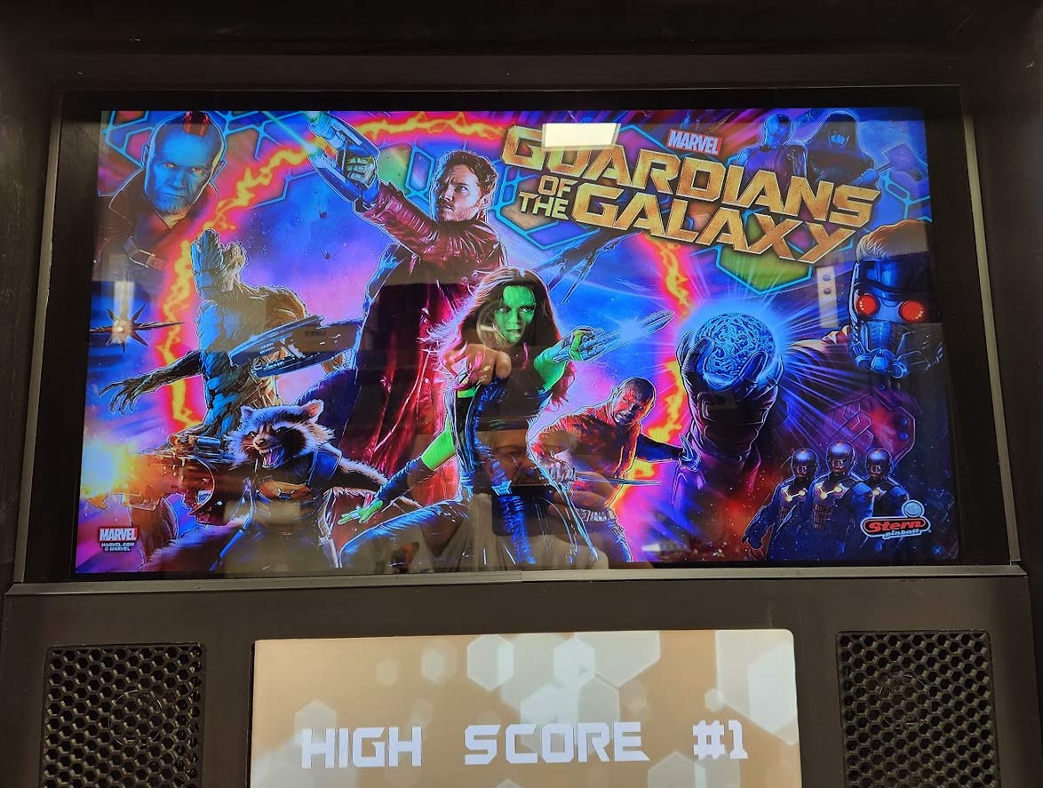
I had already decided that my system would include a 32″ backglass monitor, a 19″ DMD monitor and a 43″ 4K playfield monitor. The RTX3060 had 4 outputs, so I was now looking for displays. I already owned a new 43″ 4K LG TV, having bought it for my garage in February 2022, and I had an old 19″ Dell monitor up in the attic, but didn’t know if it would work as it hadn’t been powered up in 10 years. I still needed the backglass monitor.
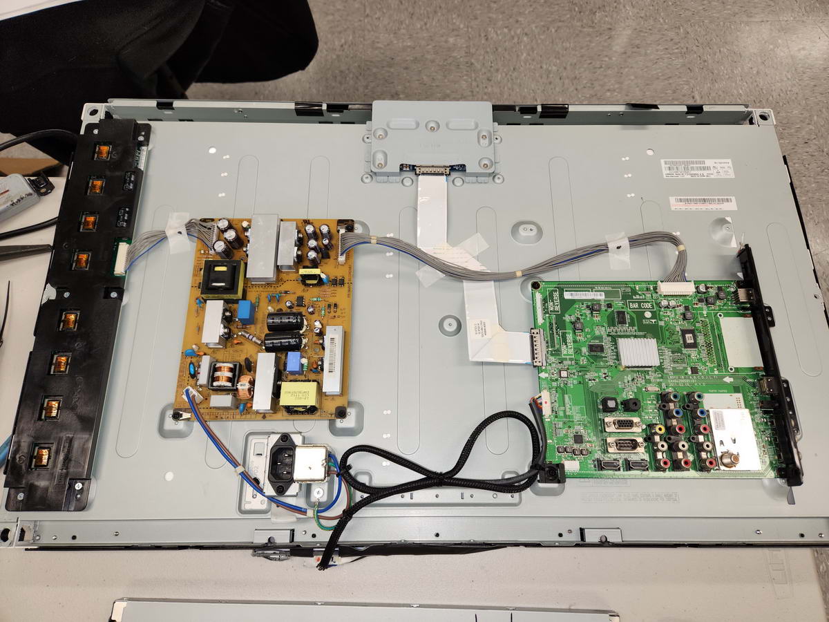
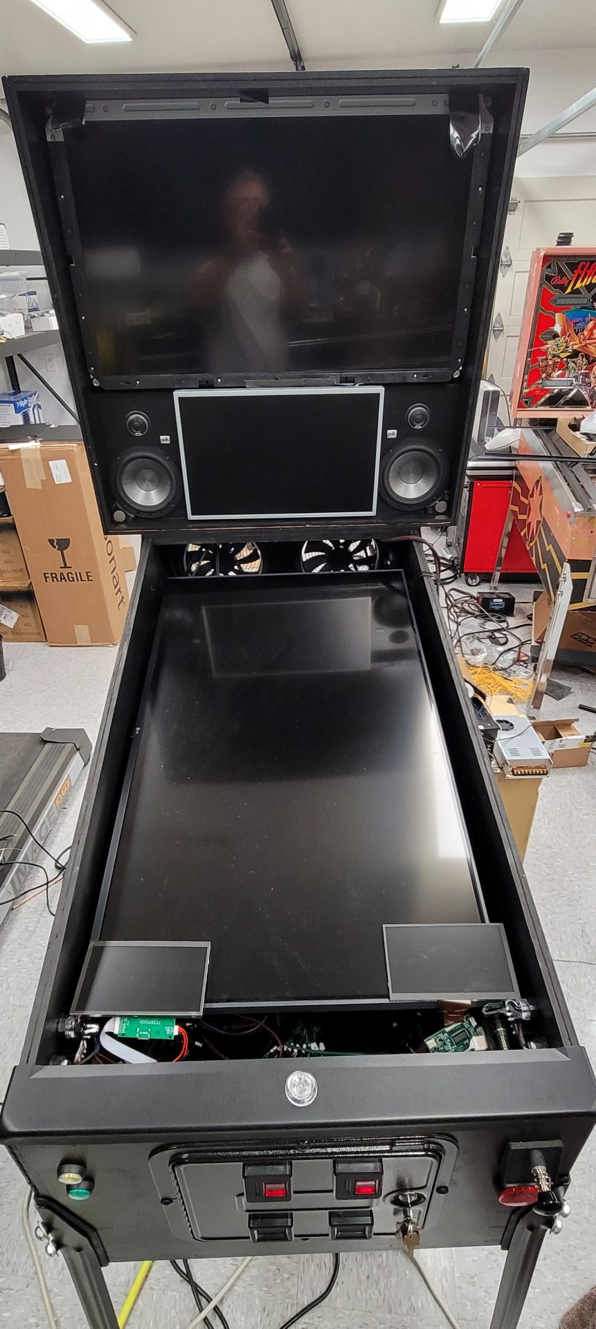
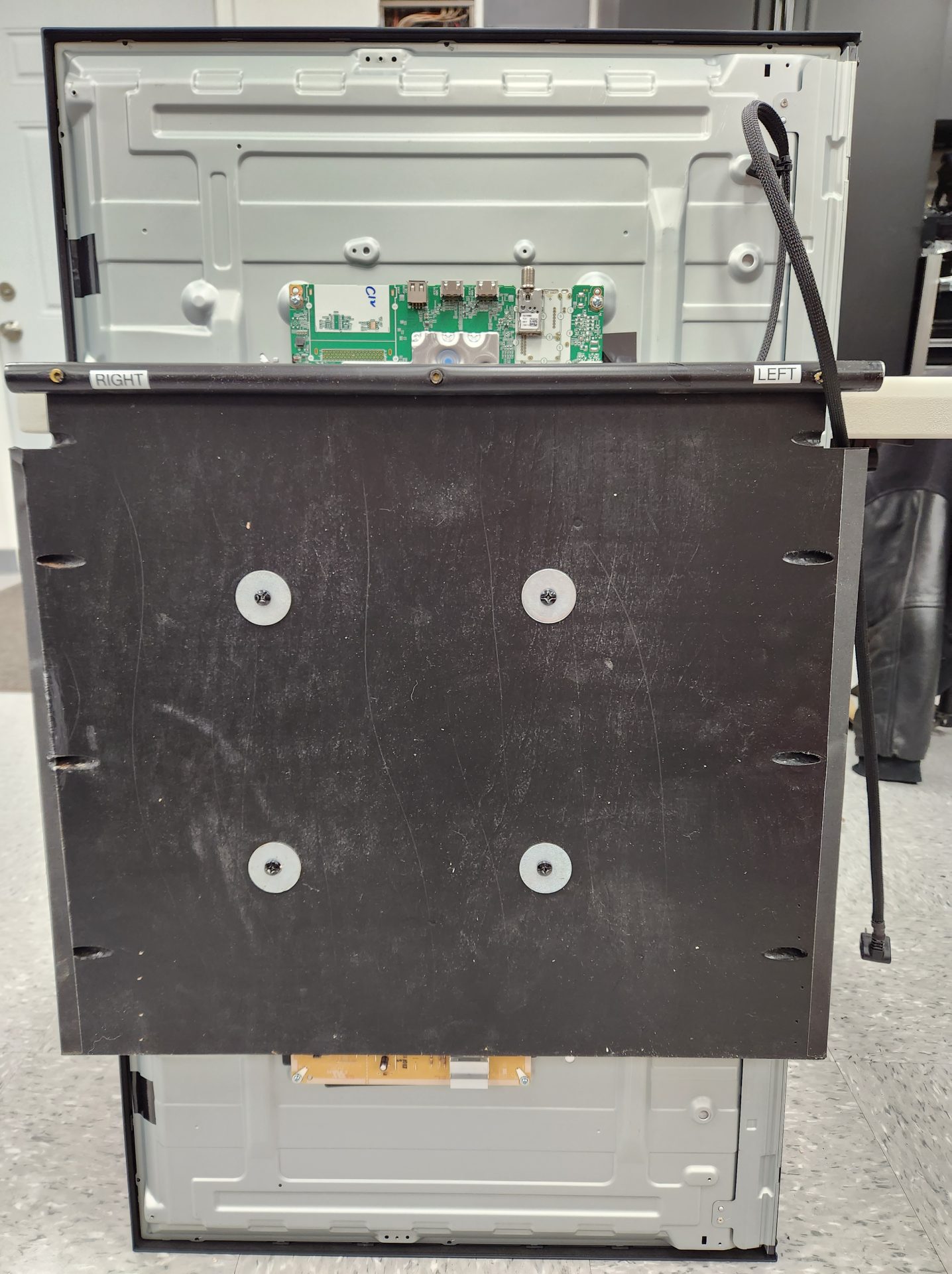
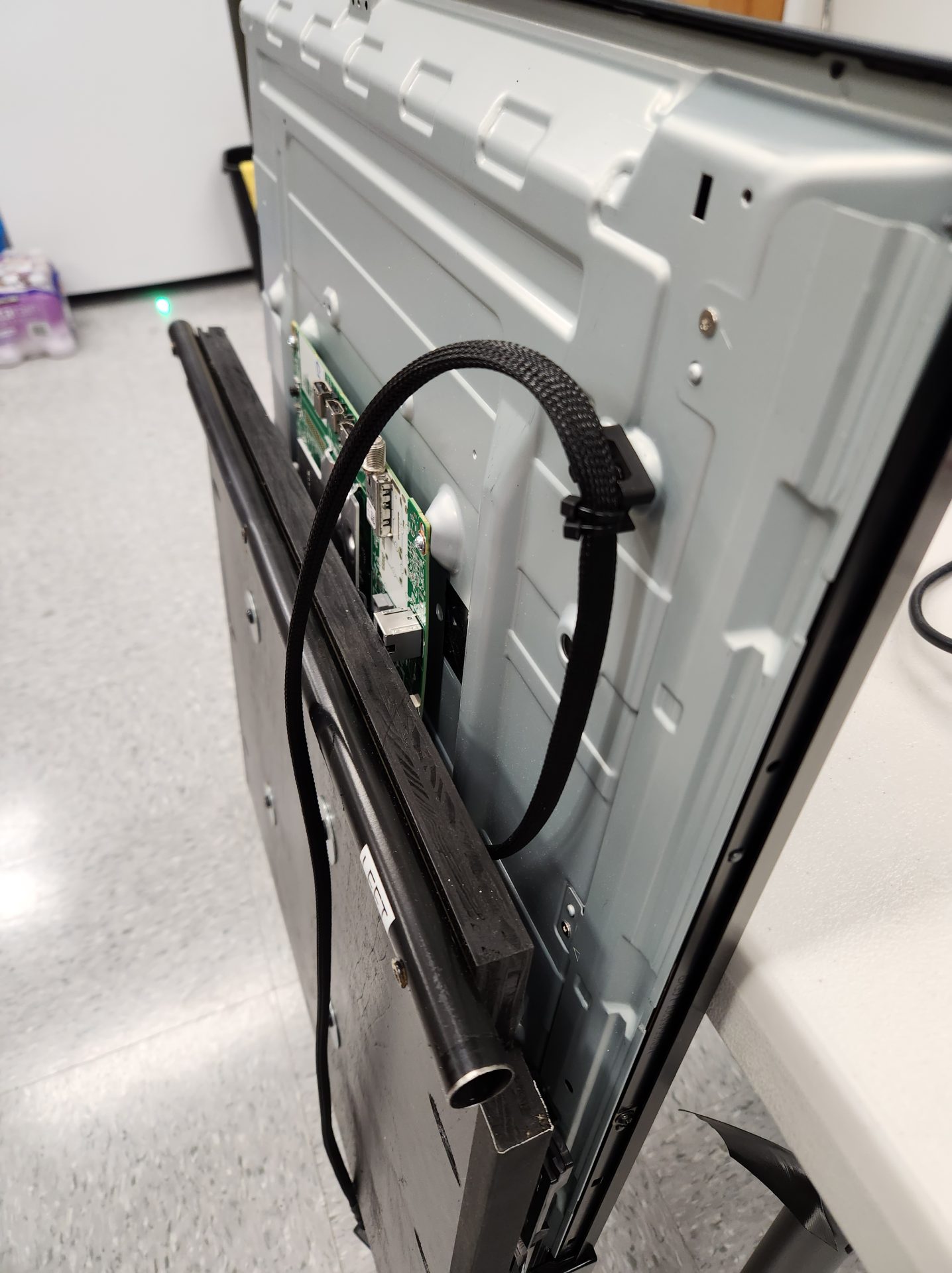
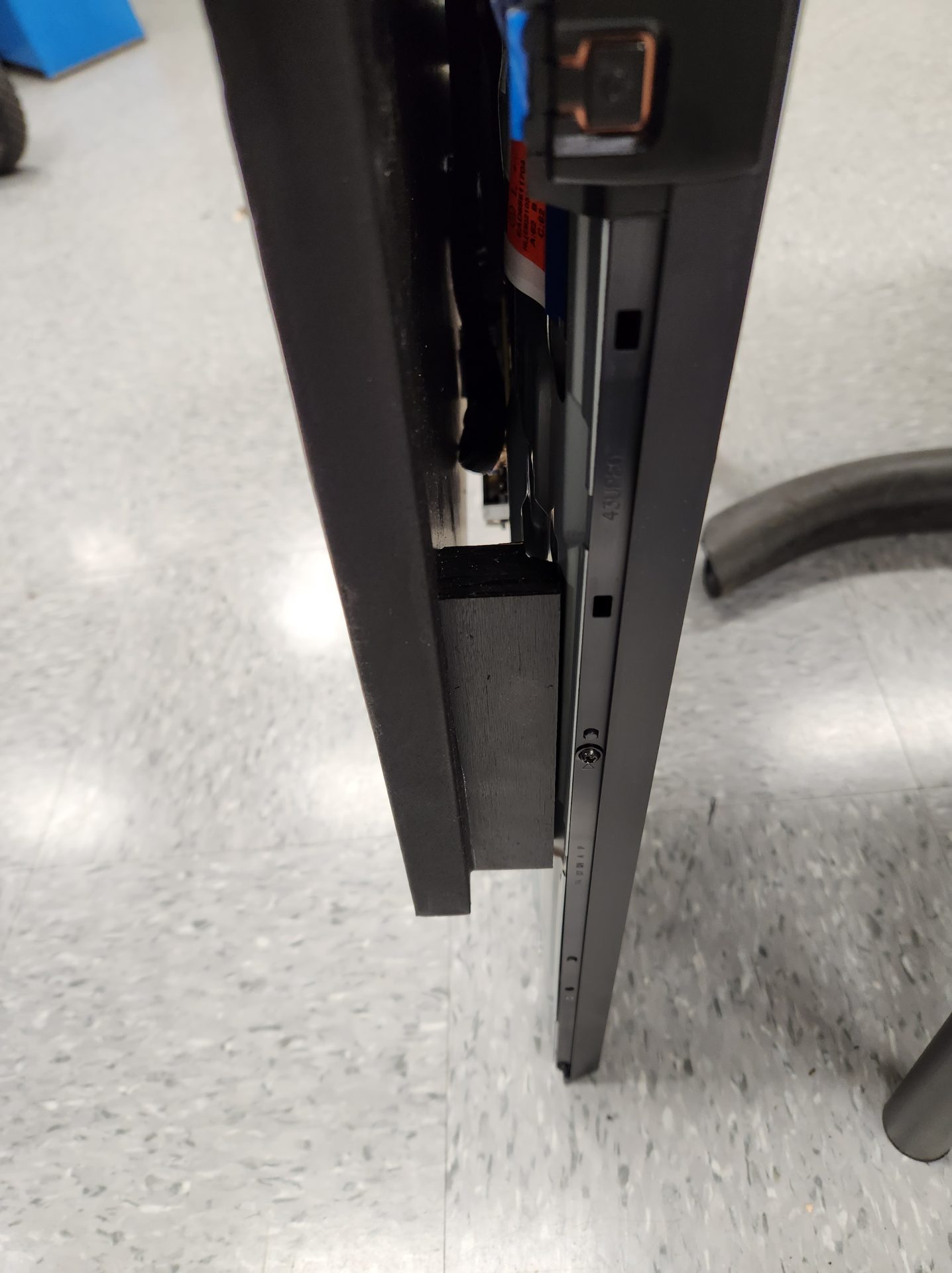
Although the cabinet design I finally ended up with may not have required me to de-case the LG 43″, I did anyway and found that it actually did make things simpler overall due to having access to the guts of the screen which made mounting the screen and routing of wires easier. It also helped in being able to shore up some areas that needed support once the screen was laid down flat.
When I connected the Dell, it turned out to be dead, so I figured what the hell – I couldn’t screw it up any worse than it was, so I pulled it apart to take a look. Turns out it had a pregnant capacitor on the board, so I scrounged through some old components and scavenged a cap to replace it – voila! – it came on and worked like a champ! Since this was going to be used as the DMD and size was definitely a factor, de-casing it was the way to go, but since the case is what actually held the board components to the screen, I had to use some metal tape to get them to be all one piece again, and the black metal bracket was the part that allowed it to hang from the mount I made in order to locate it in the backglass:
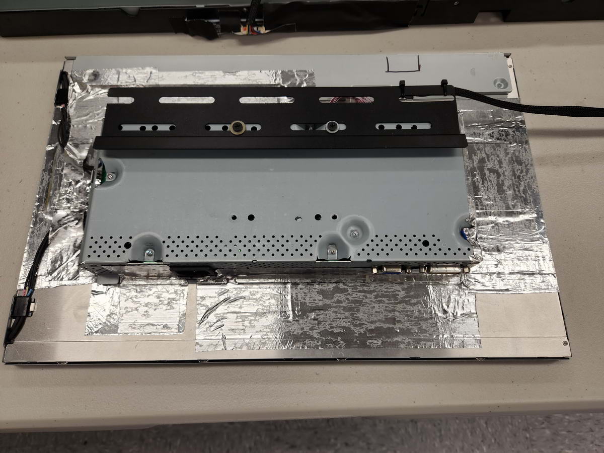
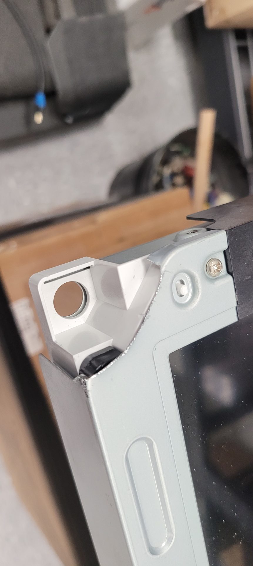
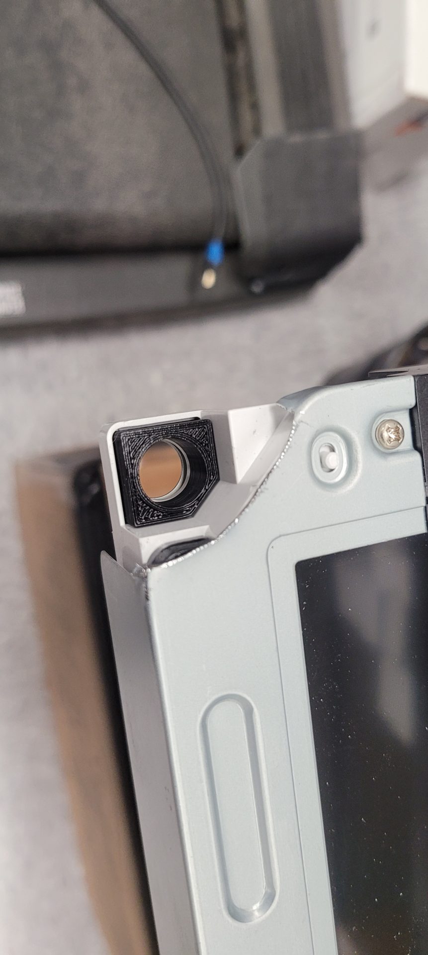
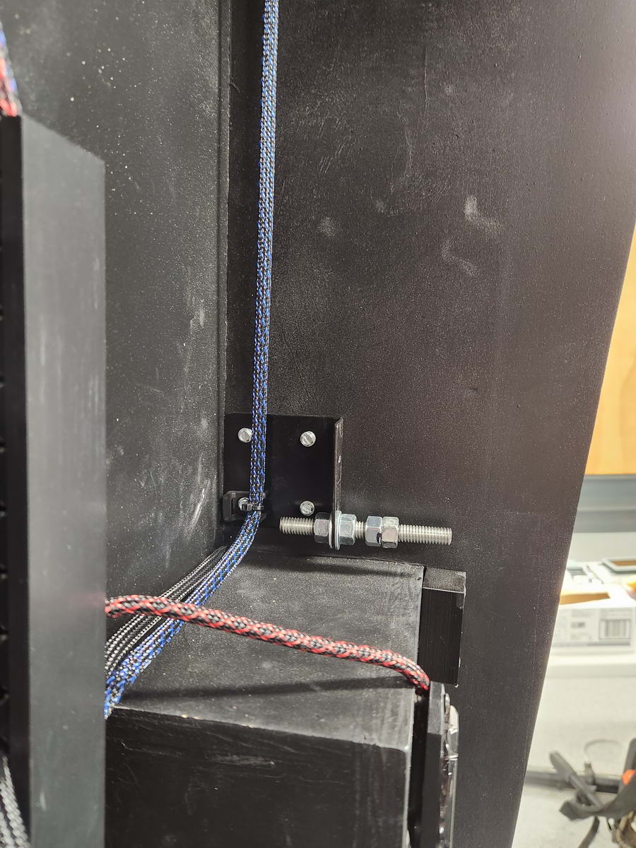
Checking out Craigslist, I found a 32″ Samsung TV that someone was selling for $60 and made that purchase. De-casing this was also necessary, as the screen would have been too wide to fit with the case on. After pulling the case off, the VESA mount came with it, so it was great to see that there were large holes in all four corners – this allowed me to add 4 studs to the backglass box to mount the monitor instead of a VESA mount, and that method also allowed fine-tuning of the mounting depth of the monitor, which made the install of the backglass box glass panel MUCH easier to accomplish:
The holes in each corner were very recessed, so much so that the nuts that were used to bolt it down were too far in to get a socket on it, so I ended up 3D-printing some washers to space out the mounting surface:
 |
 |
Since I own my own car audio company, I have lots of old audio and video equipment hanging around, and I decided to investigate what it would take to add apron screens using some of the old video components from some older headrest video systems I had in stock. The Rosen headrest system had 7″ screens that seemed to be the right size to allow me to not take up too much room in the apron while still allowing the 43″ monitor the space it needed as the playfield, so I de-cased two of the 7″ monitors and used HDMI to RCA input adapters to feed them, as the systems only had RCA inputs. This ended up being not optimal as the conversion from HDMI to RCA sucks, and the video quality suffered. To resolve the image quality and resolution problem, I ordered some HDMI input boards from China and mocked them up on the bench – they worked great and the 800×480 resolution was more than enough to let these monitors work for instruction cards on the apron:
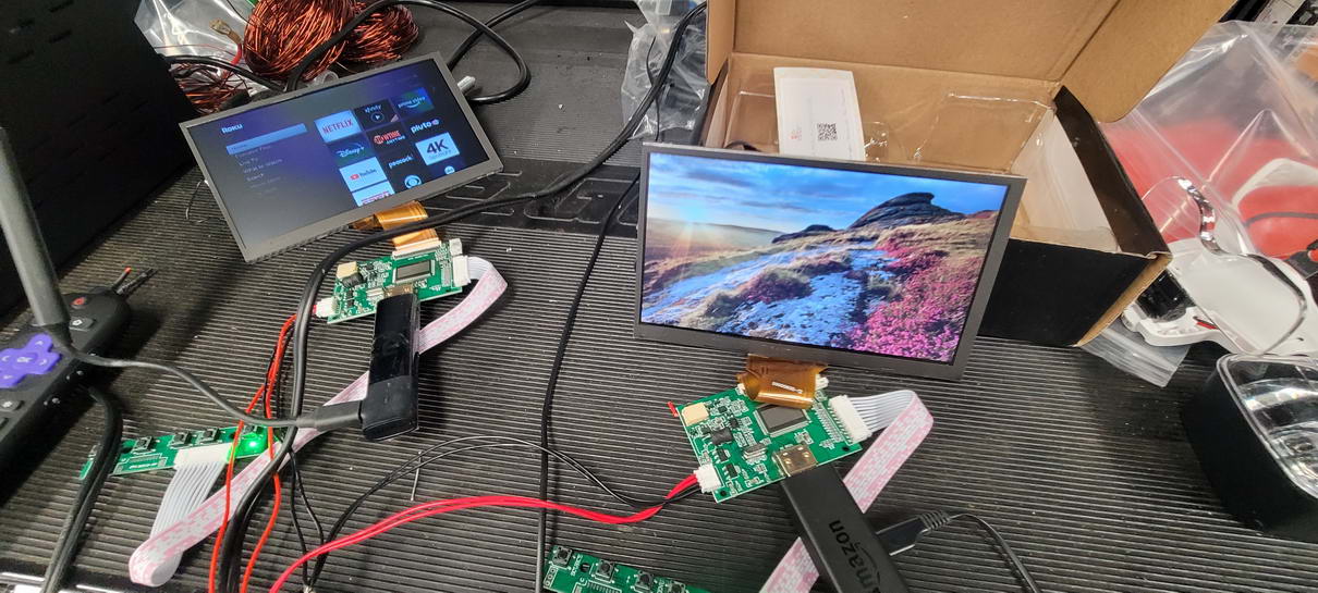
After I mocked these up, I got a great deal on some closeout 8″ Rosen overhead DVD players, so once those arrived, I pulled them apart to see if they would work – since they did use the same ribbon cable input as the 7″ monitors, the HDMI input boards would work on them as well. Although I did build a panel for the 7″ monitors, I ended up using the 8″ monitors in my final build (more on that later):
Once all of the monitors were added and working, it was on to the haptic portion of the build. In order to make this thing look and feel like a real machine, it needs feedback devices added to the cabinet and triggered via software by each game. For this build, I made the decision to repurpose the parts from Tom Tom for the feedback on the VPB machine. This meant taking all of the pop bumpers, flippers, slingshots, bells, knocker and gear motor from Tom Tom and making them all work for this project. I know this will extremely piss off some guys, but the way I see it is like this: since that machine was in such bad shape and I had neither the time or patience to even try to bring it back to life, I could make parts of it live again in this build, and at least feel like it served a higher purpose…
Re-using those parts was daunting in a way, since I had no idea what it took to accomplish it, but after reading up on how it was done, I sourced a couple 24VDC and 12VDC power supplies to provide power, an LED Wiz and a set of SainSmart 16-relay modules to get it all going. The LED Wiz is what takes the output from the Direct Output Framework software that interprets the individual haptic and lighting outputs from each game, but the LED Wiz by itself could not possibly run the solenoids directly, so it sends negative triggers out to the SainSmart to do the actual switching of the 12 or 24VDC to run each feedback device when it’s called for in the game.
Once DOF was set up and programmed for each channel’s output to the SainSmart modules, I mocked up the Tom Tom parts on the floor next to the table to verify it all worked – all devices were running on 24VDC, giving very strong output, but I dialed back the pop bumpers and slings to run on the 12VDC supply to keep from chewing up the relay contacts – the flippers remain on 24VDC, but with some mods that let them function with low voltage when held open – more on this later. It was pretty awesome to see each of the devices trigger properly and operate! :
- (2) flippers
- (4) slingshots
- (4) pop bumpers
- (1) gear motor
- (1) knocker
- (2) bells (hi and lo)
- (1) tilt bob
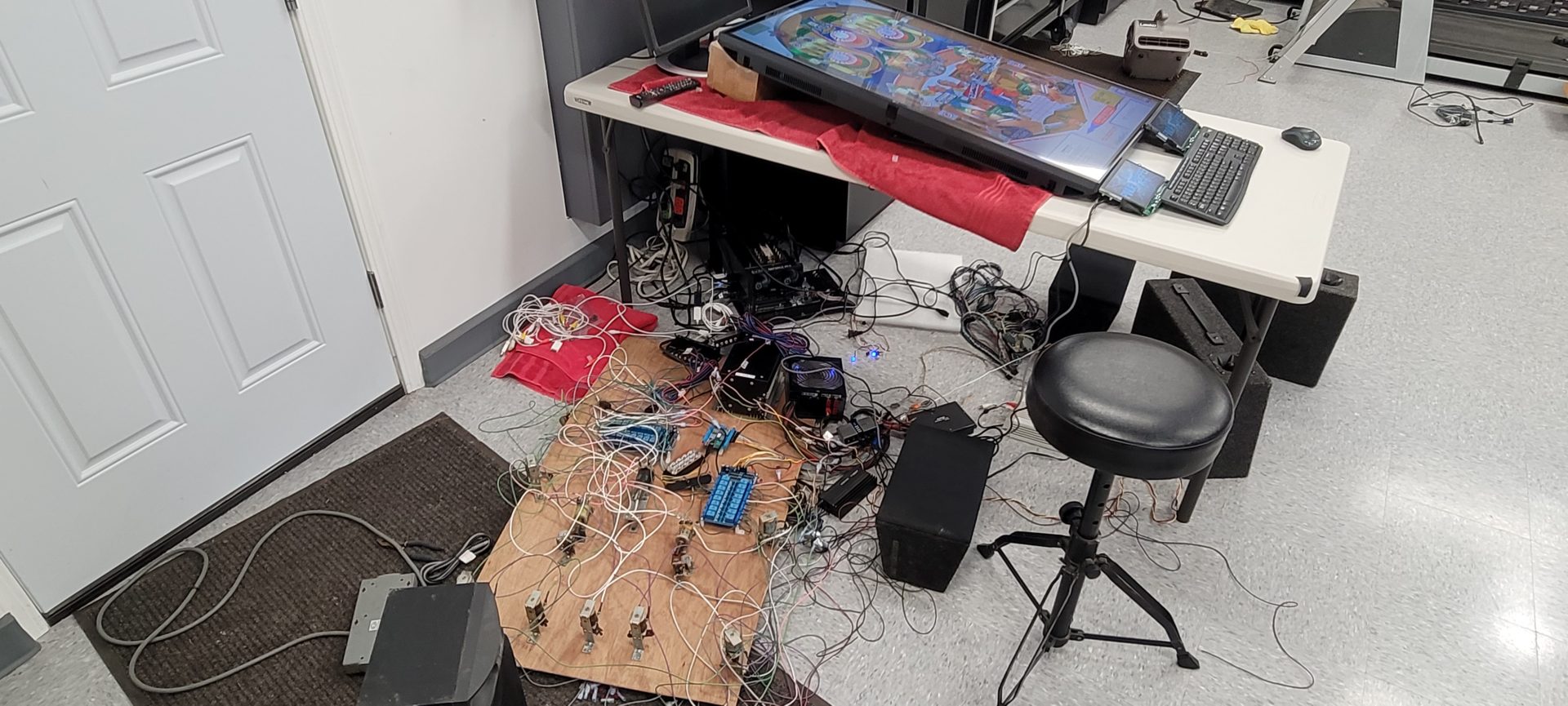
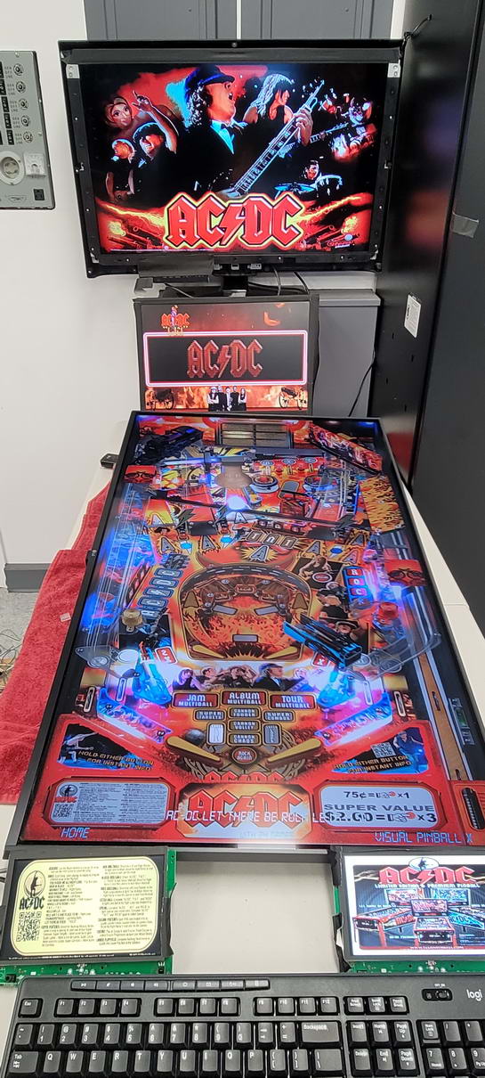
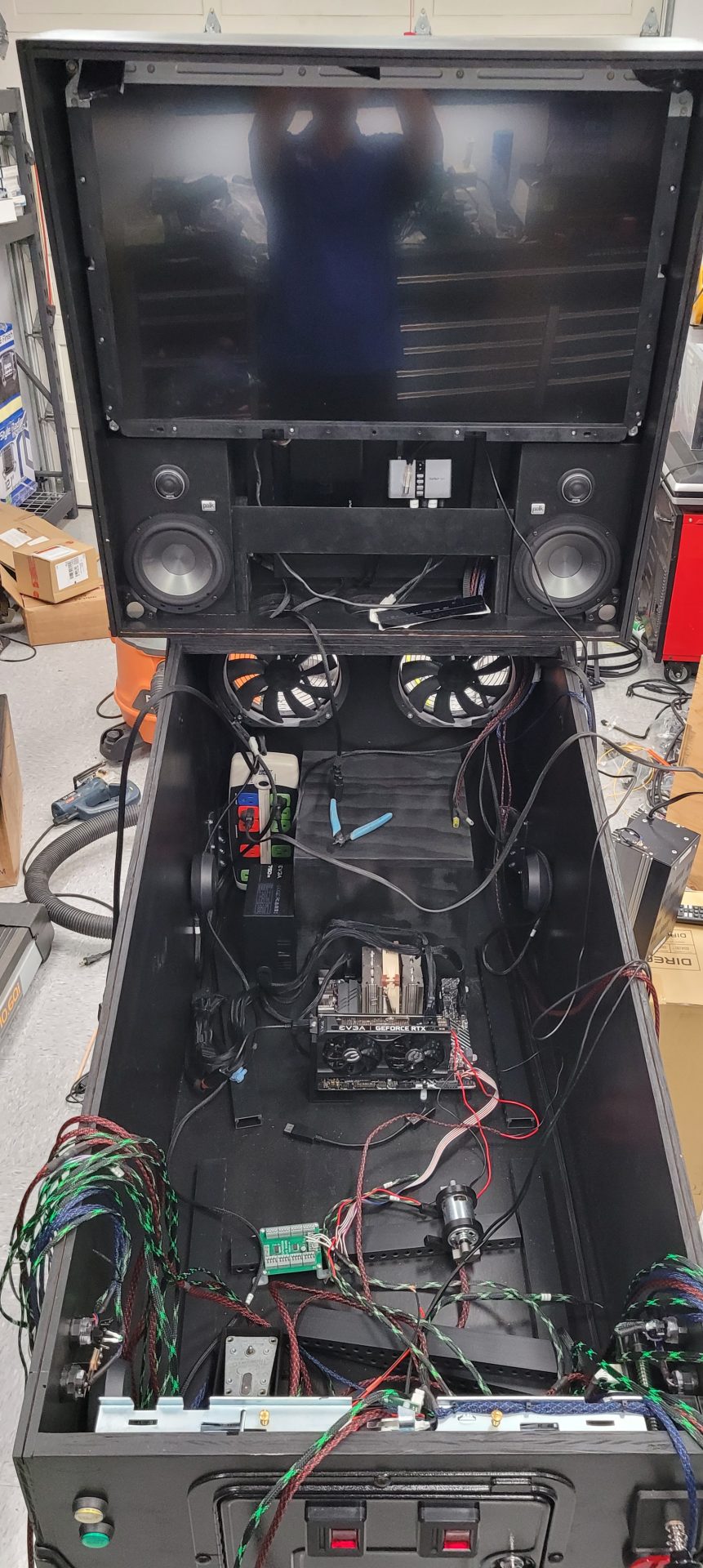
So, 45 days or so into the project, I had a working pinball machine set up on a table in my garage, with the 32″ backglass, 19″ DMD, 43″ 4K playfield and two 7″ apron screens:
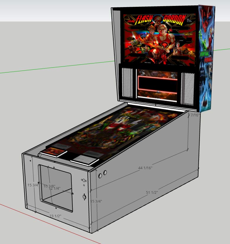
Now to start down the path of building the cabinet to house everything. Of course, I wanted a full-scale pinball machine, and the measurements of the playfield monitor dictated that it would have to be a widebody cabinet – 23 1/2″ wide internal dimension. I watched a ton of YouTube videos and luckily Emil Jurica (The Way of the Wrench) was starting his series on building the cabinet, so I watched and learned a TON from him, including mocking the whole thing up in Sketchup. I downloaded his plans and started to learn the program.
Sketchup is a great online CAD program that allows you to build just about anything virtually and make design changes prior to cutting a piece of wood. It allows you to do all of your measurements very precisely and fit together all of your parts to insure it will work the way you intend, as well as the ability to output a cut list, making your time at the table saw as productive as possible. The learning curve is a little steep, but once you get the hang of it, it is a VERY cool tool to use to design your project without making a bunch of costly mistakes when it comes time to start cutting.
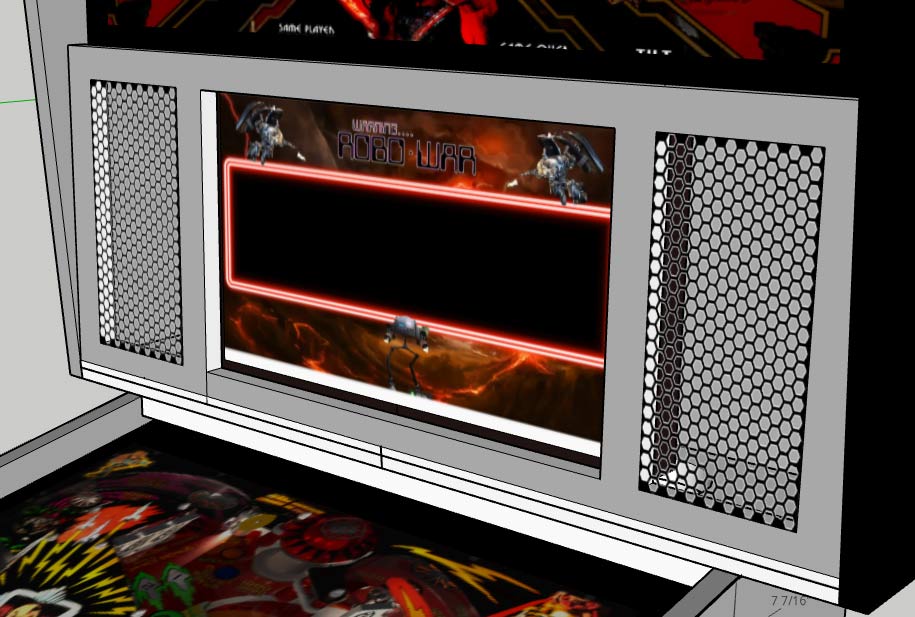
I had to modify Emil’s plans a bit because my cabinet was not going to be as wide and the backglass box and DMD/speaker grille were going to be a different design, but with Sketchup, that was all relatively easy to do. After about 3-4 days of design and modification, I came up with this plan (graphics were just to get an idea of what it would look like in real life):
While this was going on, I had ordered the widebody “Ultimate Cab Builder’s Kit” from VirtuaPin: https://virtuapin.net/index.php?main_page=product_info&cPath=9&products_id=35&zenid=3rgbtl18dvjknk2c627u0207q0
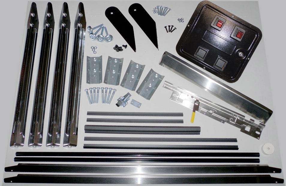
I opted for adding the button kit, fire button lockdown bar and standard coin door, all in textured black powder coat. The cool thing about the fire button on the lockdown bar is that it is RGB and will be able to light up in colors associated with each game. This kit included all of the hardware to build the cabinet, along with backglass trim. By the time this was all totaled, the entire package shipped to my door was $860. Could I have done it cheaper? Yes, but the parts look SO FRIGGIN COOL! The whole kit was shipped in a way that shows those guys definitely know what they are doing, and I highly recommend that you take a look at this kit – it just takes a lot of the hassle out of rounding up all the parts you need for the project.
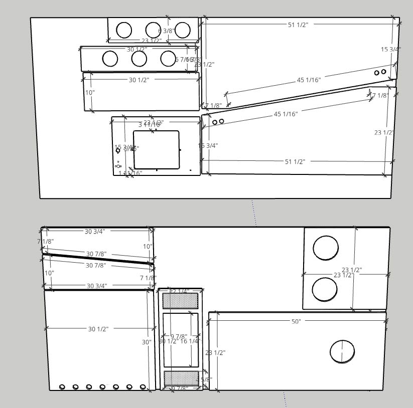
Once those parts arrived and I could verify all of the measurements, I printed the cut list, bought two sheets of 4x8x3/4″ maple plywood at Lowe’s and started cutting. Although I guess it is technically possible to do a basic cabinet from one sheet, mine needed two, and left plenty of scrap to use for the various additional small parts that were going to be required as the project progressed:
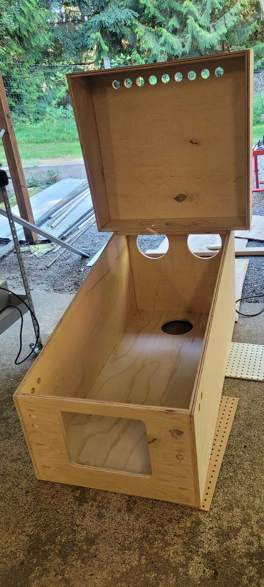
Once the big pieces were cut, I was able to start assembling things, which was a HUGE step after doing the planning for a month and a half! Once things actually started coming together, I could make design decisions with real wood and a tape measure instead of doing it on a monitor – MUCH more satisfying! I used Emil’s method of fastening the box together – using the Kreg joinery system (which I already owned) and a lot of glue, and this allowed a much stronger (I feel) build and made the corners much easier to assemble, as it didn’t require doing dados or using router bits – just a standard butt joint and lots of Kreg screws. The entire project soaked up almost 200 screws, and with the corner braces in place that were required for the legs, it is not lacking in strength! Prior to adding any of the hardware, the cabinet looked just like my plans. I used a router to cut the two holes for the two 200mm fans in the back of the cabinet and a drill press to add the vent holes at the top of the back box:
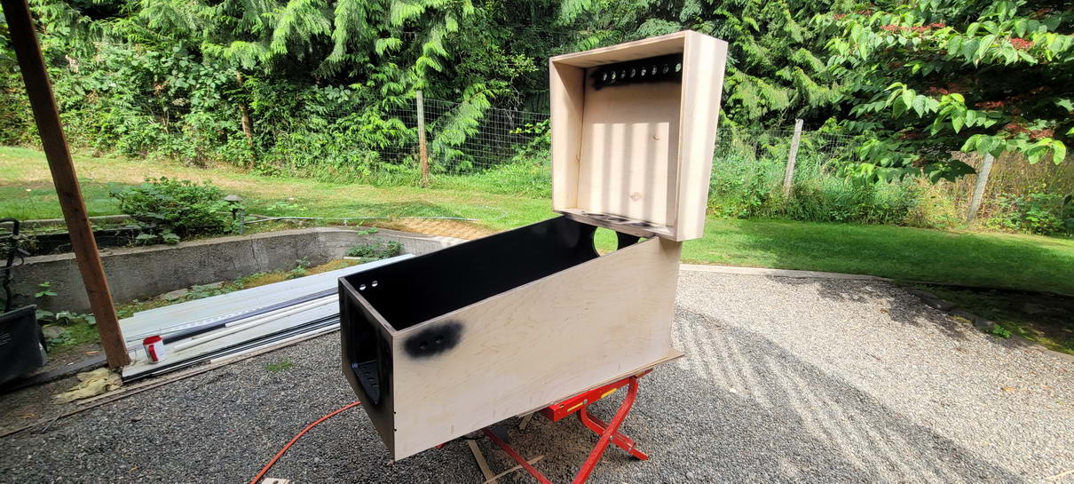
I knew that the entire cabinet was going to be black prior to adding graphics, so I grabbed a black rattle can and started painting, but soon realized how much paint this whole thing was going to take – A LOT! So, I used my HVLP paint gun and some of this stuff: https://www.lowes.com/pd/Krylon-Satin-COLORmaxx-Black-Enamel-Interior-Exterior-Paint-Actual-Net-Contents-32-fl-oz/1000459833 – it worked GREAT! If you thin it down with some water and use your paint gun, it goes a LONG way – I used just over a pint to do the whole cabinet with 4 coats, for under $25! Compared to doing it with rattle cans, I’m sure it would have taken 8-10 @ $8 ea., so the savings in paint were enough to buy the paint gun (if I didn’t have it already).
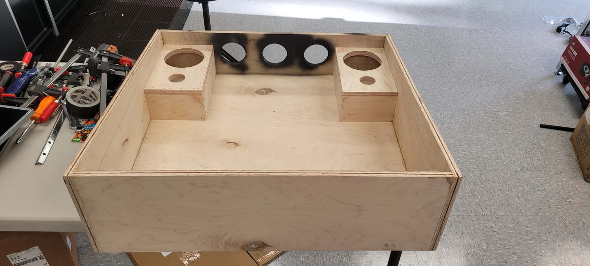
As a car audio guy, one of the requirements for this project was that it had to sound as killer as possible, so the design for the backbox was going to incorporate a set of Polk Audio MM6502 separates that I had bought for my truck but never used. These include a 6.5″ woofer and 1″ tweeter with their own passive crossovers. To be able to mount these in the backbox meant building a box to house them, which was easy to do, but meant that I had to anticipate how all of the components that would rely on that space of the backbox would be mounted and situated in order to not have to keep pulling out the speakers for access or having to modify the whole design once it was all bolted together. The other parts of the build that used that space were:
- Backbox hinge hardware
- T-Nut for the backbox hold-down bolts
- T-Nut for the DMD monitor mounting plate
- Strobes
- Magnet holders for DMD grille
Having decided what all of these things required left me with building the boxes like this – the depth of the boxes were determined by the DMD/speaker grille assembly – the DMD monitor was going to be mounted on a frame and it would be fitted almost flush to the finished surface of the grille assembly, while the rear of the grille assembly needed to be somehow attached to the speaker boxes – more on that later:
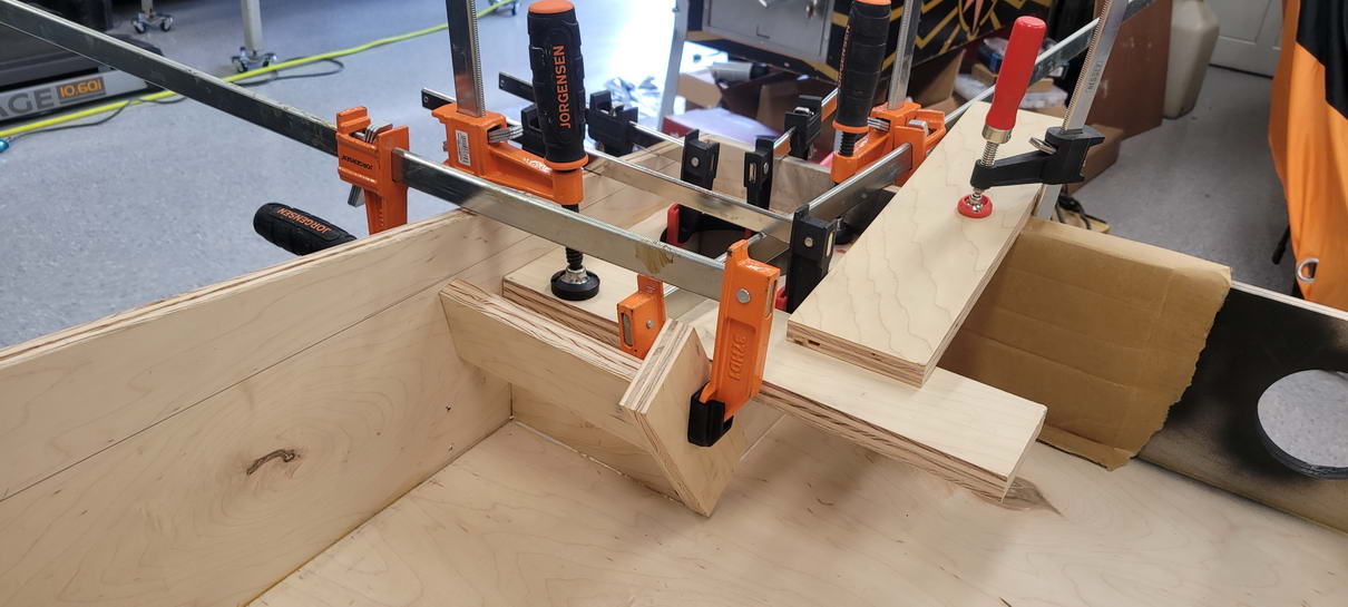
Gluing them in without having to drill holes in the outside of the backbox required a crazy combination of clamps :- ):
Once the backbox was all assembled, one thing that was very noticeable was that the top panel of the box had a pretty significant bow – about 1/32-1/16″ low in the middle, and that was not going to work since it would be the thing I would notice every time I looked at it, so I took an extra piece of steel “L” channel left over from a garage rack system and bolted that across the top inside of the backglass box to stiffen the panel. This completely removed the bow and made a mount for the upper two studs that would hold the 32″ backglass monitor: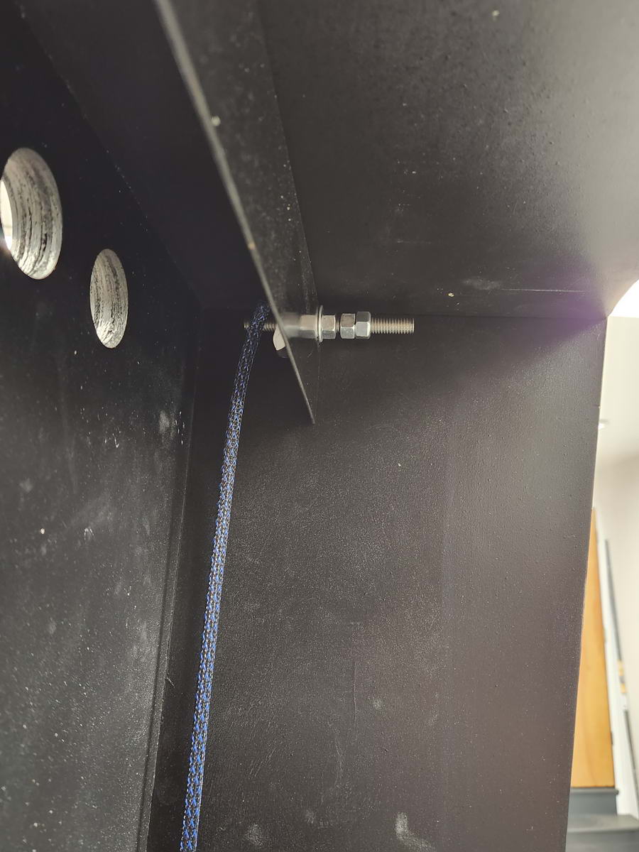
Once I had the upper mounts for the 32″ monitor in place, it was easy to fab and mount the lower mounts – these were just steel “L” brackets with the studs attached:
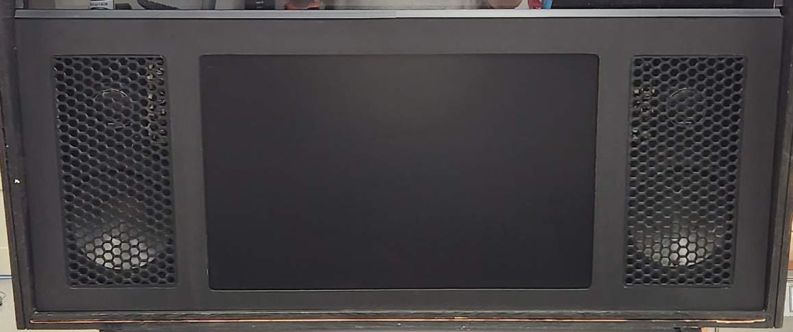
The separate speakers I used required a fairly tall grille, which I wanted to model on the Stern speaker design, and with the DMD monitor fitting inset and almost flush to the grille, I decided to source some black laminate to cover the grille, which would solve a few issues:
- Clean surface to either paint or add graphics to
- Serve as a very thin “stop” to allow the DMD monitor to be inset virtually flush with the surface
- Serve as a stop for the grilles to be inset virtually flush
The final design of the grille was going to look something like this (with the back side of the 3/4″ plywood panel routed out once the laminate was installed and trimmed), with a slot in the upper edge to accommodate the back glass and channel:
After looking around for pre-made grilles that fit my measurements, it was becoming apparent that to do what i wanted to do would require a 3-D printer, since I could make the part EXACTLY what I needed to fit the design, without having to compromise anything. So, I bought a Creality CR10-V3 printer and filament to start printing my own parts. This turned out to be a HUGE decision, as this project ended up with well over a dozen 3D-printed parts that I would have never been able to source elsewhere – mainly be cause they didn’t exist except in my own head! Designing and printing my own parts did require learning even more CAD and adding other 3D printing-specific software, but overall it was a win due to being able to think of something, design it and print it and have a solution for the problem done in a day, rather than waste time trying to find something i would have to modify to fit anyway…
Although the file to print the grilles was available on Thingiverse, I made the grille larger and MUCH thicker (5mm) than the plan online in order to give it more strength and have it look a little better and fit the design. After the grilles were printed, I measured and cut the DMD grille assembly for the monitor and speaker grille holes on the table saw and jigsaw (using a guide for straight lines):
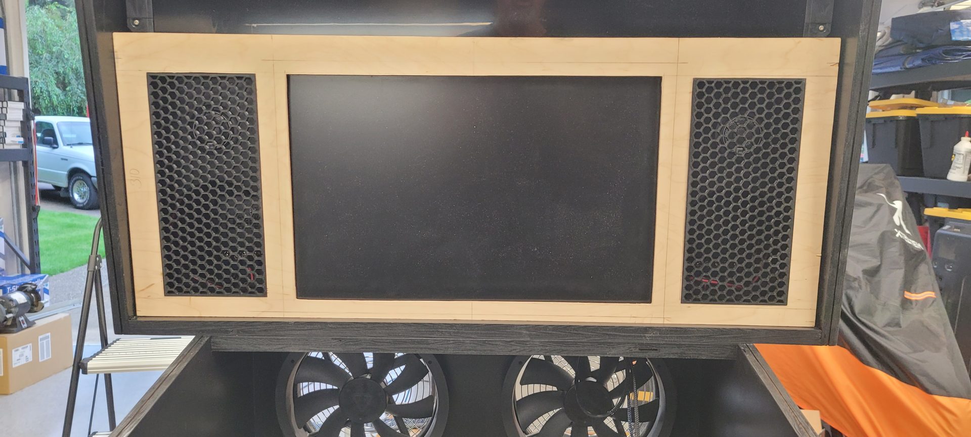
Once these were cut and the parts fitted to insure a good fit, I covered the panel in laminate, then trimmed out the holes with a trim router, leaving nice rounded corners in each hole. Now the panel had to be routed out from the back side to inset the grilles and the DMD monitor. I built a makeshift router table from an old bench and clamped a fence on it to allow straight feeds, then using the plunge router, steadily worked my way deeper into the grille until all of the openings were routed to the level of the back side of the laminate faceplate. This now allowed the DMD monitor and speaker grilles to be butted up flush, with just the rounded corners of the laminate holding them in:
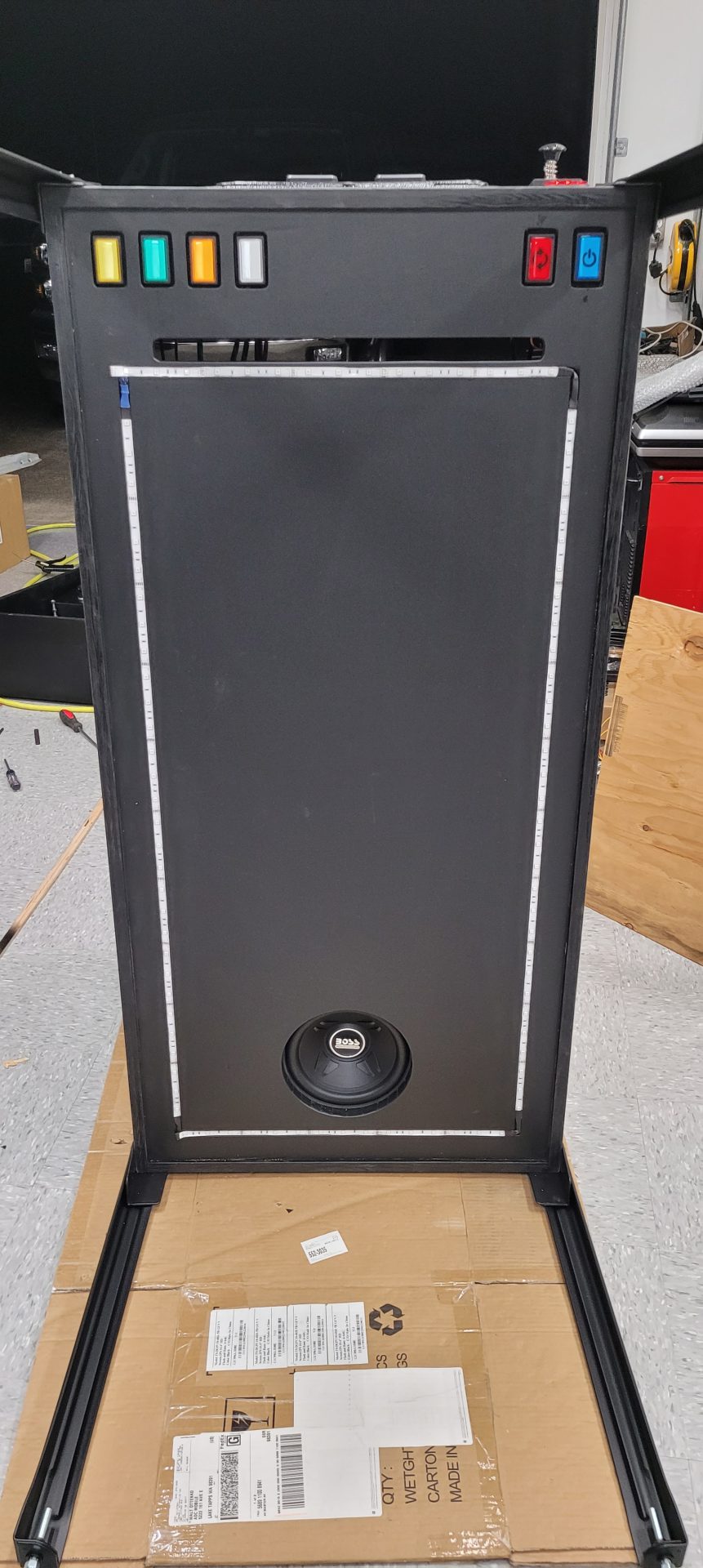
On the bottom of the cabinet, I wanted to add a slot to allow for incoming cool air that the two 200mm fans would draw across all of the PC components and power supplies, and the lighted rectangular buttons from the VirtuaPin kit were going to be flush mounted, as well as the RGB LED strip for the under-cab lighting. Since I am a car audio guy, I also wanted my subwoofer to sound great, so I made the design choice to place this toward the rear of the cabinet to get as much corner loading as possible once the machine was in place, so the 7″ hole for the 8″ sub was located at the back. The flush mounting of the buttons and LED strip meant a TON of router work on the bottom, but once it was all done and covered in black shelf liner, it looked really finished and clean:
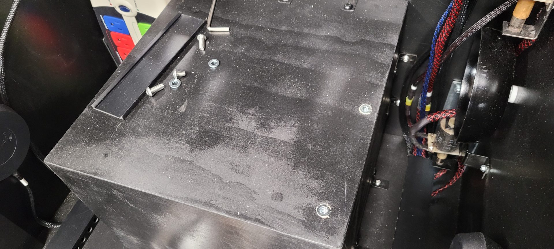
On the inside of the cabinet, it was now a big open box that I needed to fit all of the components into: PC, power supplies, haptics, buttons, plunger, subwoofer box, exciters, etc. To start with, since I knew I wanted to have great sub bass output, I built a 1 cu. foot sealed enclosure around the subwoofer. This would allow me to add a lot of power and get great response from what was an admittedly cheap Boss 8″ sub I sourced for $29 on Amazon. So, that was the first thing added to make sure everything else would fit. I sourced some threaded inserts and screws to mount the subwoofer to the cabinet instead of using wood screws, insuring that it could be removed for replacement without damaging the cabinet.
For the sub enclosure, I used the threaded 1/4″-20 inserts on both the enclosure itself as well as the cabinet, and attached it using 11 steel “L” brackets and a total of 22 bolts. I mounted the “L” brackets so they were 1/8″ short on the cabinet side, allowing each bolt to pull down tight on the bracket as it snugged into the threads in the cabinet. The enclosure is now fastened incredibly tightly to the cabinet, yet still completely serviceable. The inserts in the top of the enclosure are for the PC power supply (more on that later):
Because I wanted to be able to service everything as easily as possible, for all “screw to wood” contact in the cabinet, I used the 1/4-20 threaded inserts drilled and threaded into the cabinet which allowed the use of 1/4″-20 stainless socket head (Allen) bolts to attach everything. This meant that in order to remove any component, it was just a matter of unscrewing the socket head bolt rather than a wood screw, which over time would inevitably wear out and have to be re-drilled if it were removed more than a couple times.
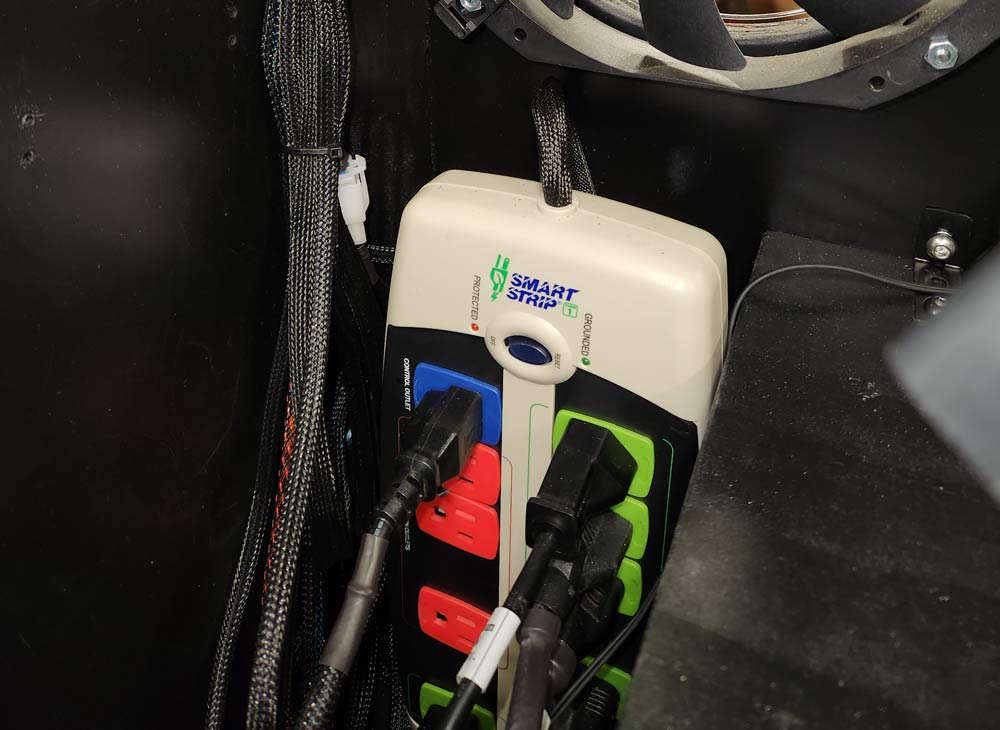
Next to the sub box in the left rear, I added the smart power strip, which uses the PC as its control to trigger on all the other components – when the PC comes on, everything else comes on – PC goes off, everything turns off. This is run from a IEC power socket w/switch embedded in the rear wall of the cabinet. I pulled the power strip apart to drastically shorten the power input wire (since it only needed to run 6 inches), and wired it directly to that input switch. This was an INCREDIBLE bitch to do, but worth it to not have a ton of excess wire floating around the cab.
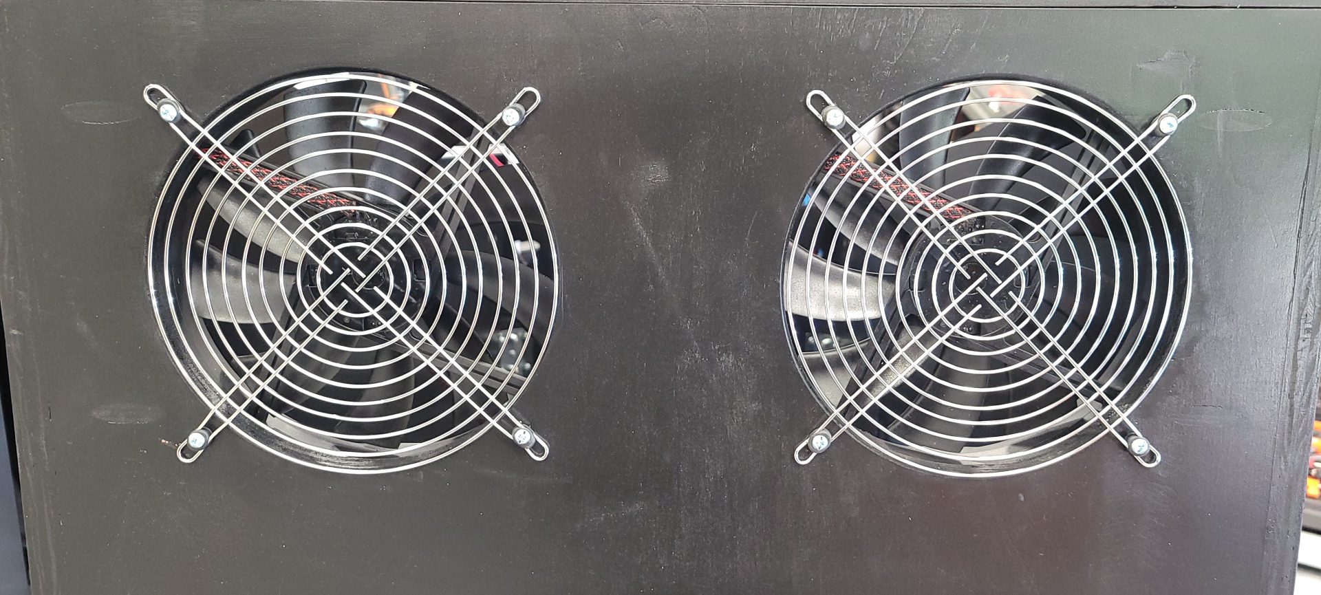
For the two 200mm fans left over from an old PC case, I routed out two holes high in the back of the cabinet and added grilles to the outside of the cabinet for protection. Because these were definitely not designed for this use case and had only short wires attached to them, I re-soldered new wires and sleeved and heat-shrank them for the run forward to the power supply. These fans move a large volume of air and work very well in this case, especially with the slot at the front of the cab providing inlet air – everything between the front and rear of the cab gets positive airflow in normal use.
As a custom car audio installer, I have always tried to make my wiring installs as clean as possible, and this was no exception. I made the decision early on to solder and heat shrink every connection, and sleeve every bit of wiring in nylon sleeving, color-coded for function:
- RED: 12 or 24VDC power/device wiring
- BLUE: 5VDC power/LED wiring
- GREEN: Control wiring (buttons, switches)
- BLACK: Video/data/speaker/120VAC
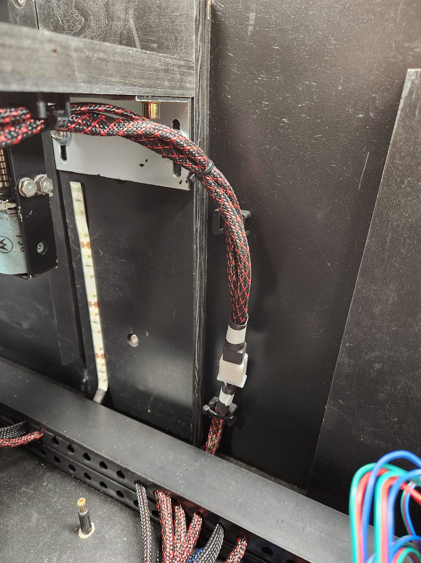
There are a few REALLY nice things about sleeving everything – since every function is color-coded, the final product looks awesome, you know immediately what “category” each wire is, and when you inevitably have to pull and re-string wires, the sleeving allows the wires to be pulled out almost effortlessly, instead of getting tangled and hard to pull, which jeopardizes your other components.
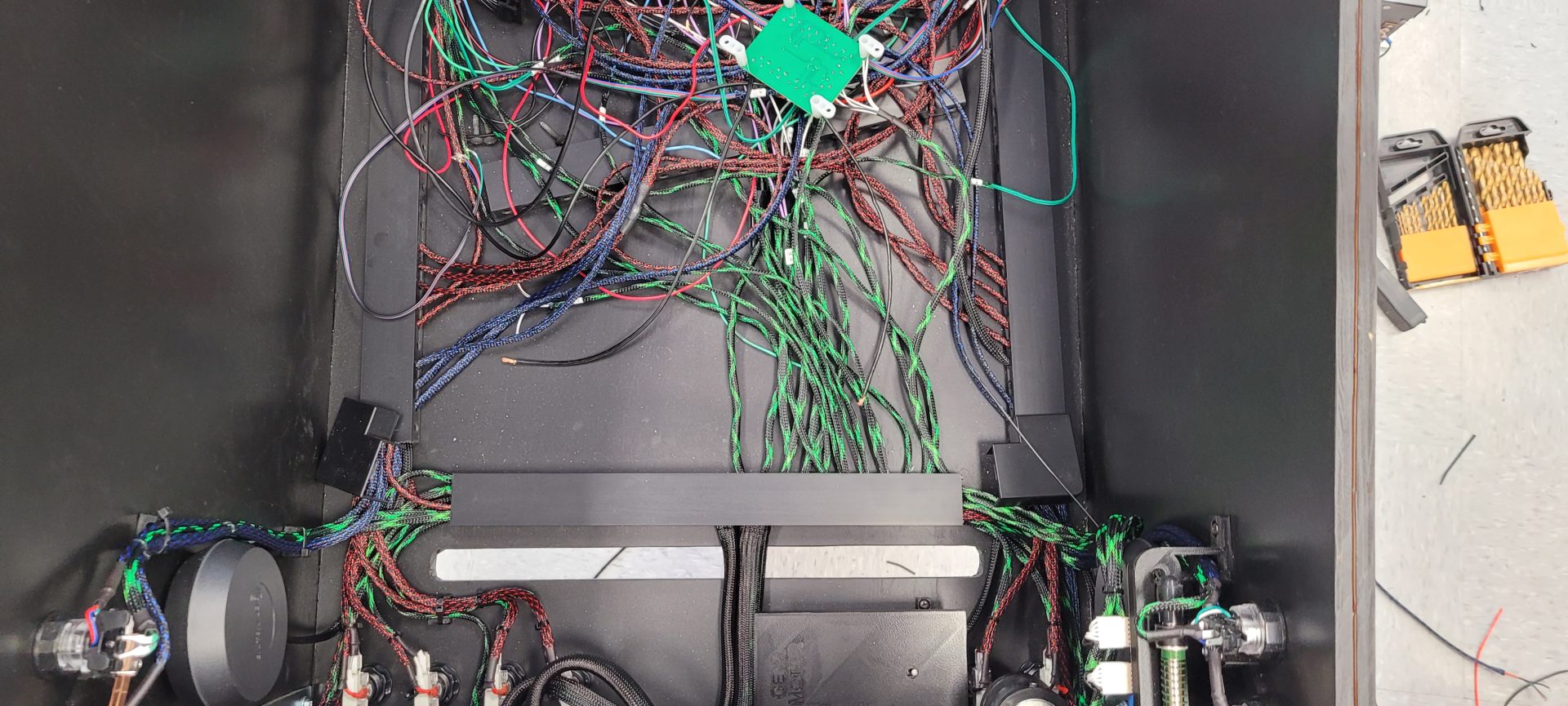
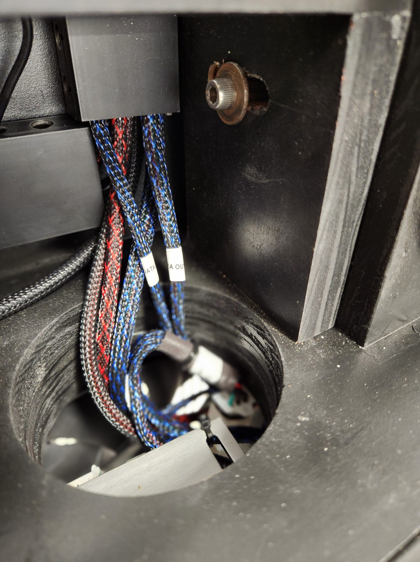
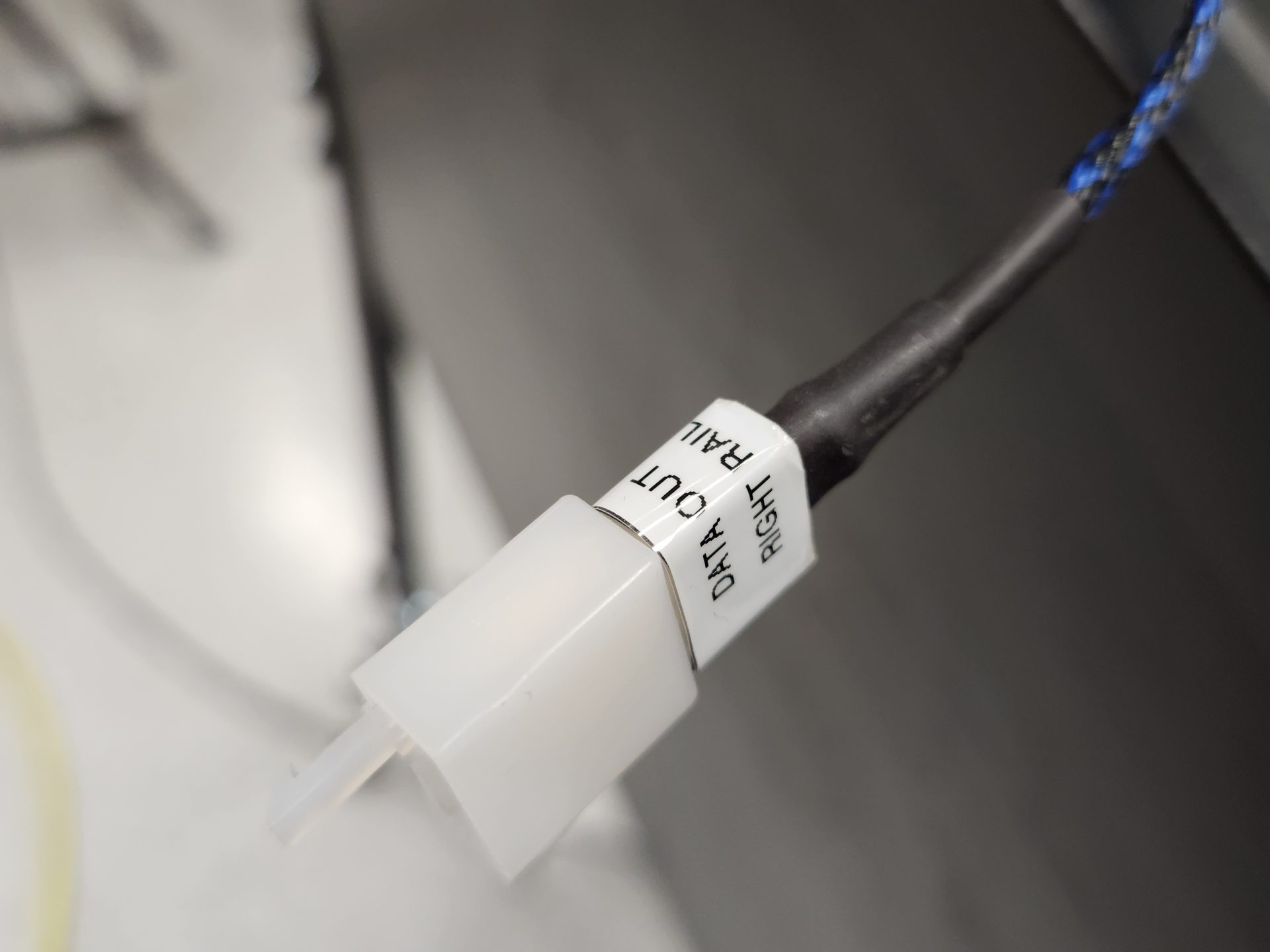
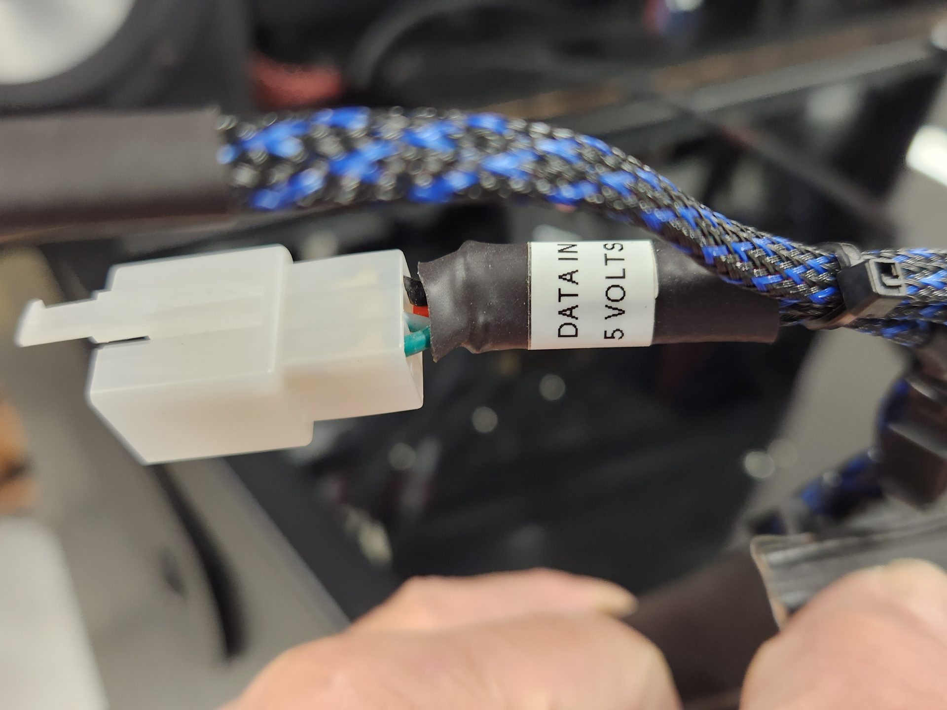
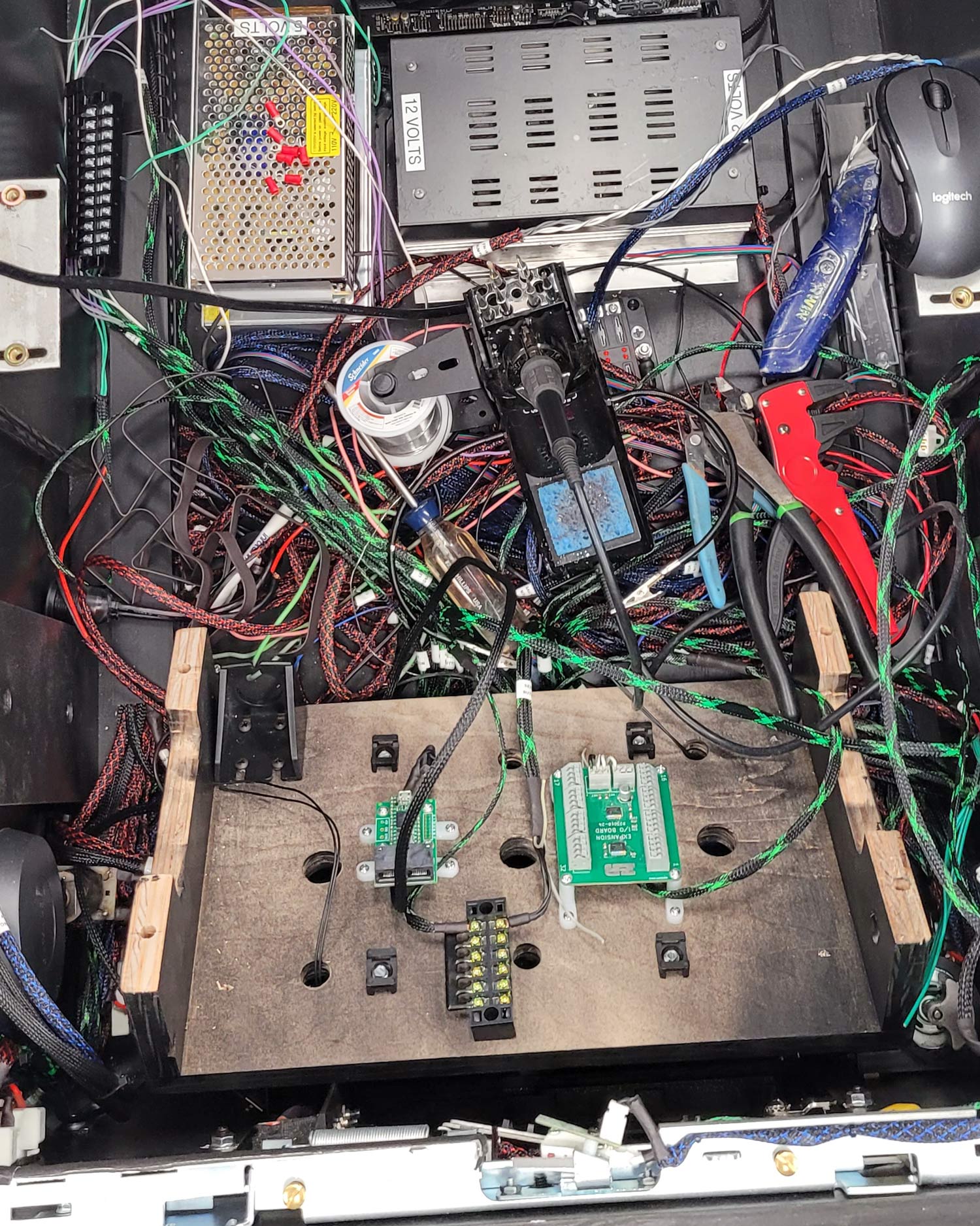
One other thing that was INCREDIBLY helpful as the project progressed was to label each wire with a Dymo label maker as it was finished and routed to its final spot in the cabinet. Even at the beginning of the project, with all wires converging into one space, all sleeved and looking very similar, it was tough to determine what was what – by the time it was finished, there was TRIPLE what was pictured here – without labels it would have made life very difficult:
Labeling each of them saved tremendous time and aggravation, not to mention the cost of blowing something up because it was connected incorrectly. In the image below, the labels are the white bands around each wire as it exits the cable raceway:
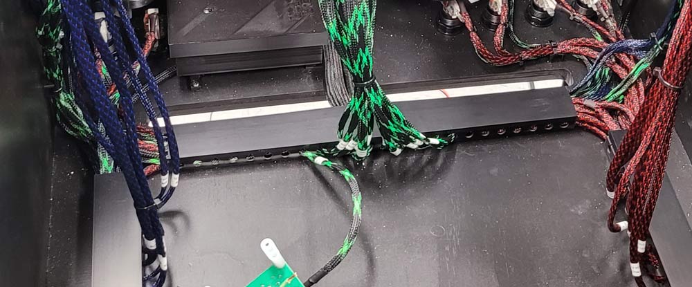
To route everything and make a clean final product, I picked up some cable raceway from Amazon that worked out really well to organize and hide the hundreds of feet of wiring in the cabinet. The build ended up with so much wiring and cabling that I ended up doing a second tier – the top level was double-stuck to the bottom tier’s caps. This was a great solution, as when you look in the cab, you really only see one run – the bottom one is hidden.
Here’s the beginning of the interior build-out showing the subwoofer enclosure, PC location, cable runs and some of the button and control wiring:
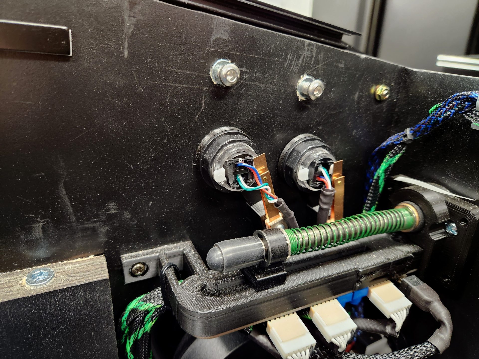
The flipper, magnasave, start and exit buttons were mounted in their places, and the coin door and plunger assembly were all installed, but all of these required customization. The start end exit buttons were lit with standard 555 bulbs, but for some reason they run on 6VDCvolts instead of 12VDC like every other button’s bulb, so those were now wired to 5VDC.
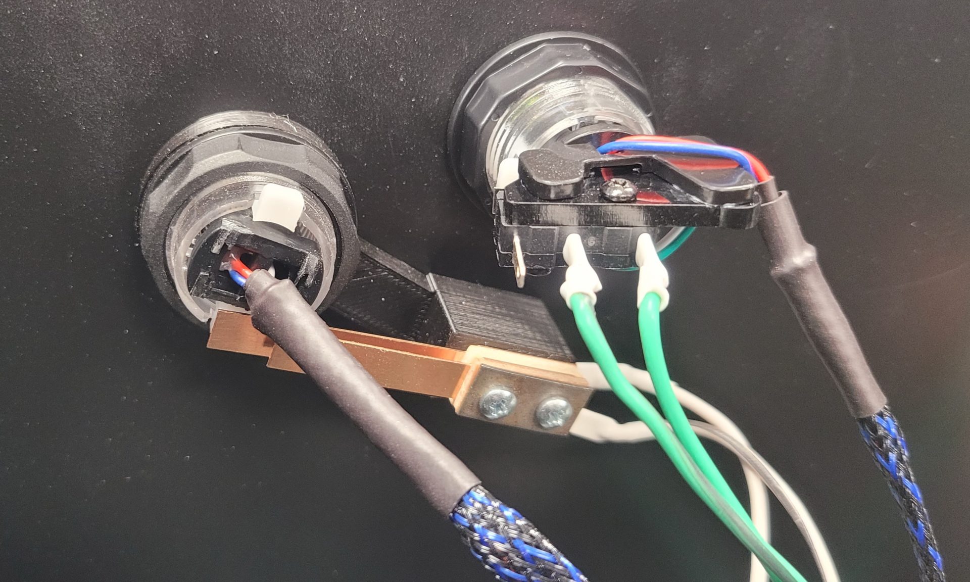
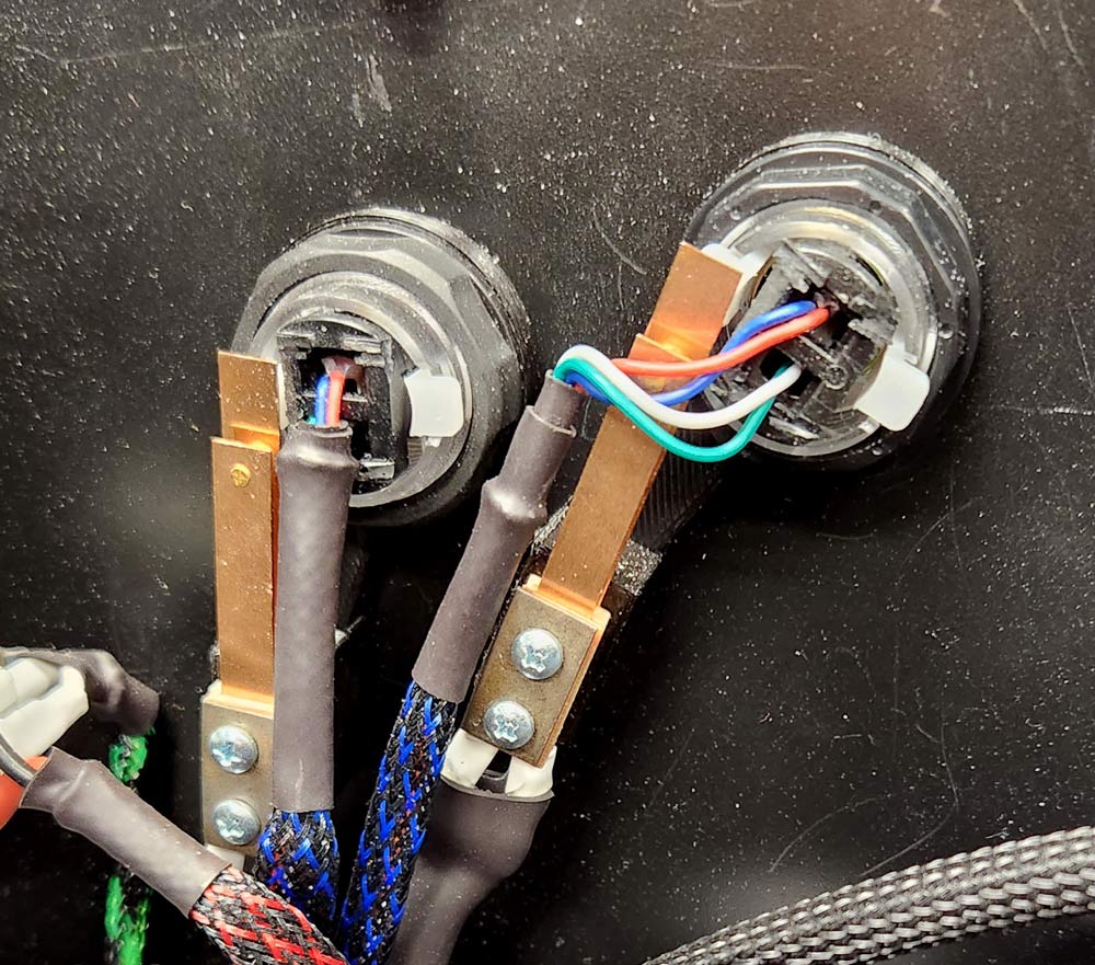
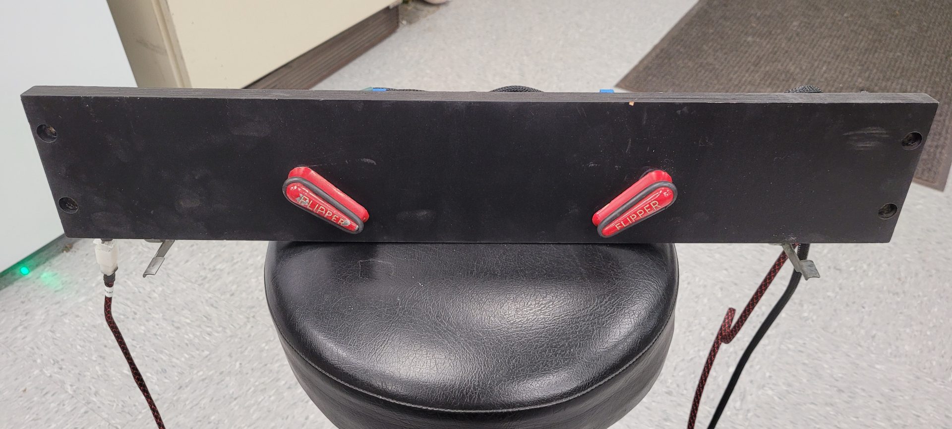
The flippers and magnasave buttons both were Spectra Eclipse RGB LED buttons, which I really like the look of, but only come with either standard “click” switches or what they call “leaf’ switches that aren’t really pinball-style leaf switches (at right in picture below). In order for these to work as a real pinball machine does, I had to add real pinball leaf switches to them (at left in picture below). This required printing rings to go around the barrel of the switch with mounts for the leaf switch. These are readily available on Thingiverse for NORMAL flipper buttons, but since mine had the center of the button taken up by the RGB LED, I had to make the leaf switch engage with the outer white portions of the flipper button only. I ended up designing the parts and offsetting the leaf switch mount 11 degrees to accommodate the design of the button and have the leaf switch engage perfectly when the button was pushed. Once one was printed to make sure of the design, I printed three more – two of which were mirror imaged for the left side.
On the coin door, I wanted to the coin release buttons to be functional (to add coins in the game), so they needed microswitches added to activate when the coin release button was pressed. Back to the 3D printer to make “L” brackets to mate with the bolt pattern on the coin door and locate the microswitches to intercept the plunger on the coin release buttons. I also wanted to emulate the service buttons, so I made a panel to accommodate the four service buttons and the control for the shaker motor, with raised text showing the function of each button:
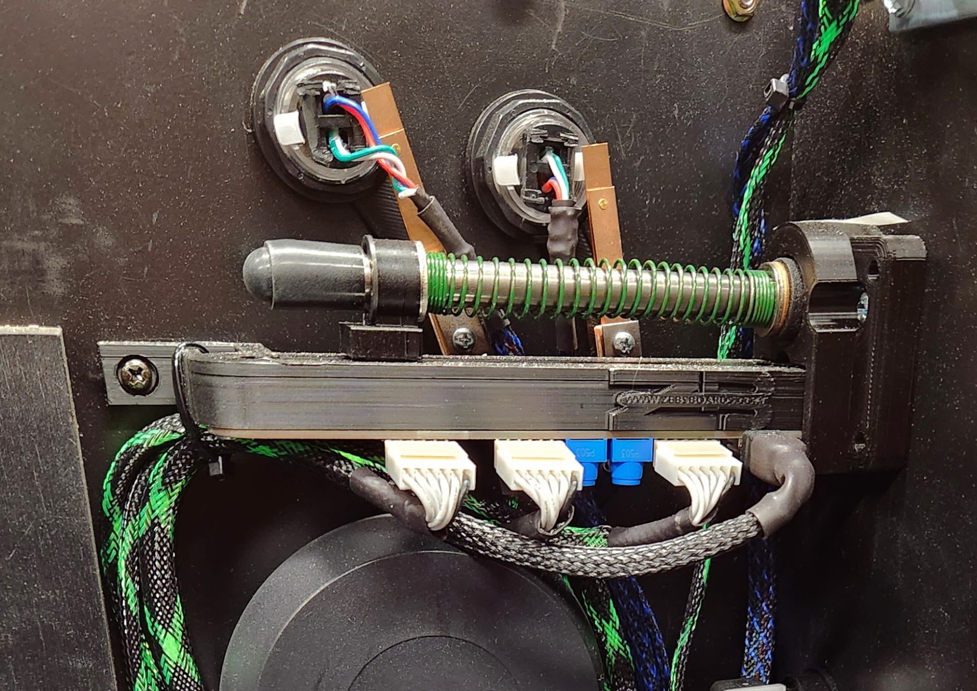
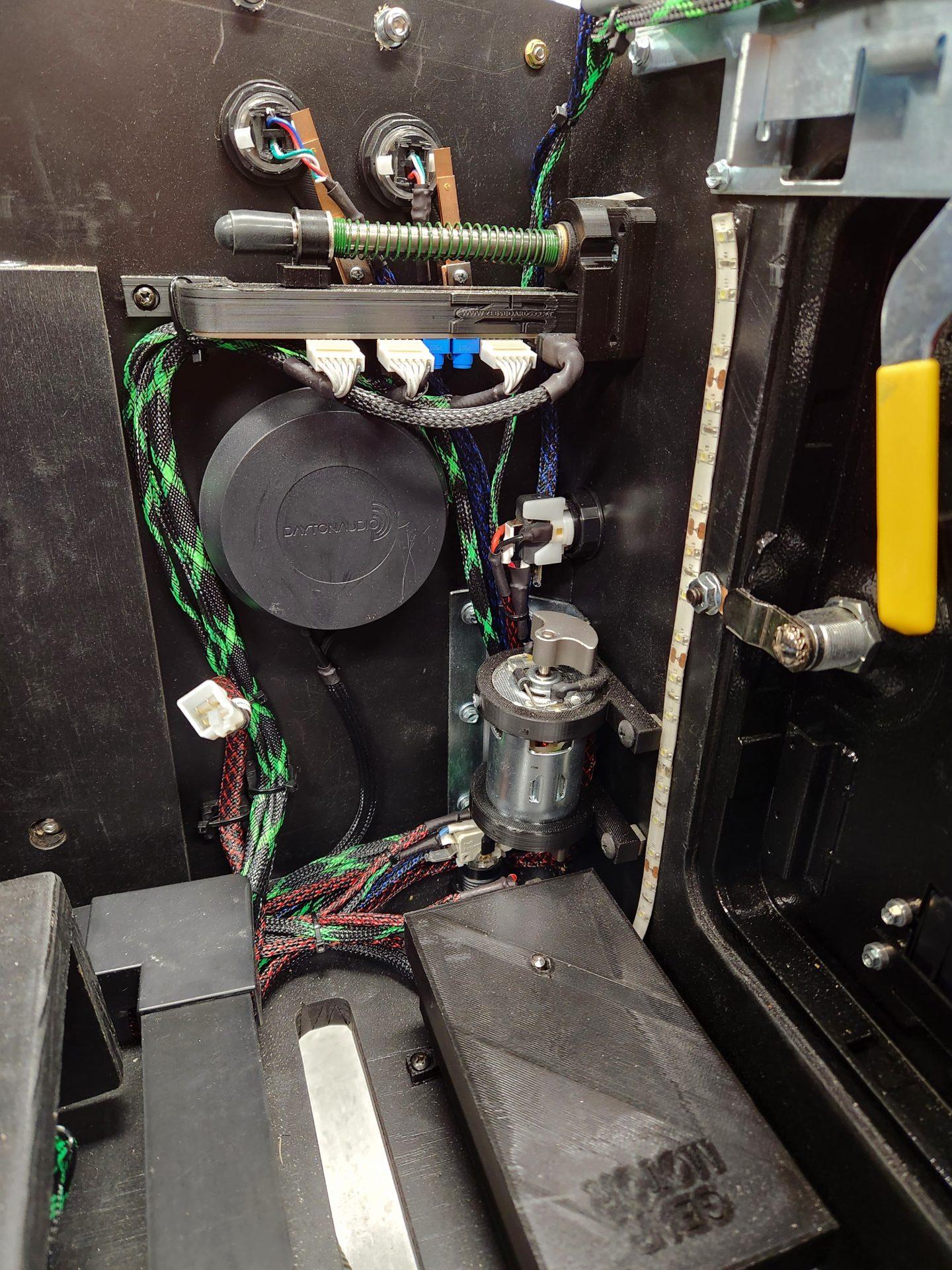
When I embarked on this project, I knew I needed a real plunger that worked as a normal pinball plunger does – pull it back to release the ball. I decided on the Plunger kit from Zeb’s Boards. Also included was the expansion board to convert all of the button inputs to keystrokes/buttons in the game. The plunger kit came with a 3D-printed part that held the large variable resistor and logic board on the plunger, but it was bright orange and completely out of character to what I wanted inside this machine. I contacted Steve at Zeb’s Boards who sent me the .stl file for the plunger, which I imported to Fusion 360 and modified to add a bracket that screwed into the sidewall and gave another place to zip-tie the flipper/mag/plunger wires:
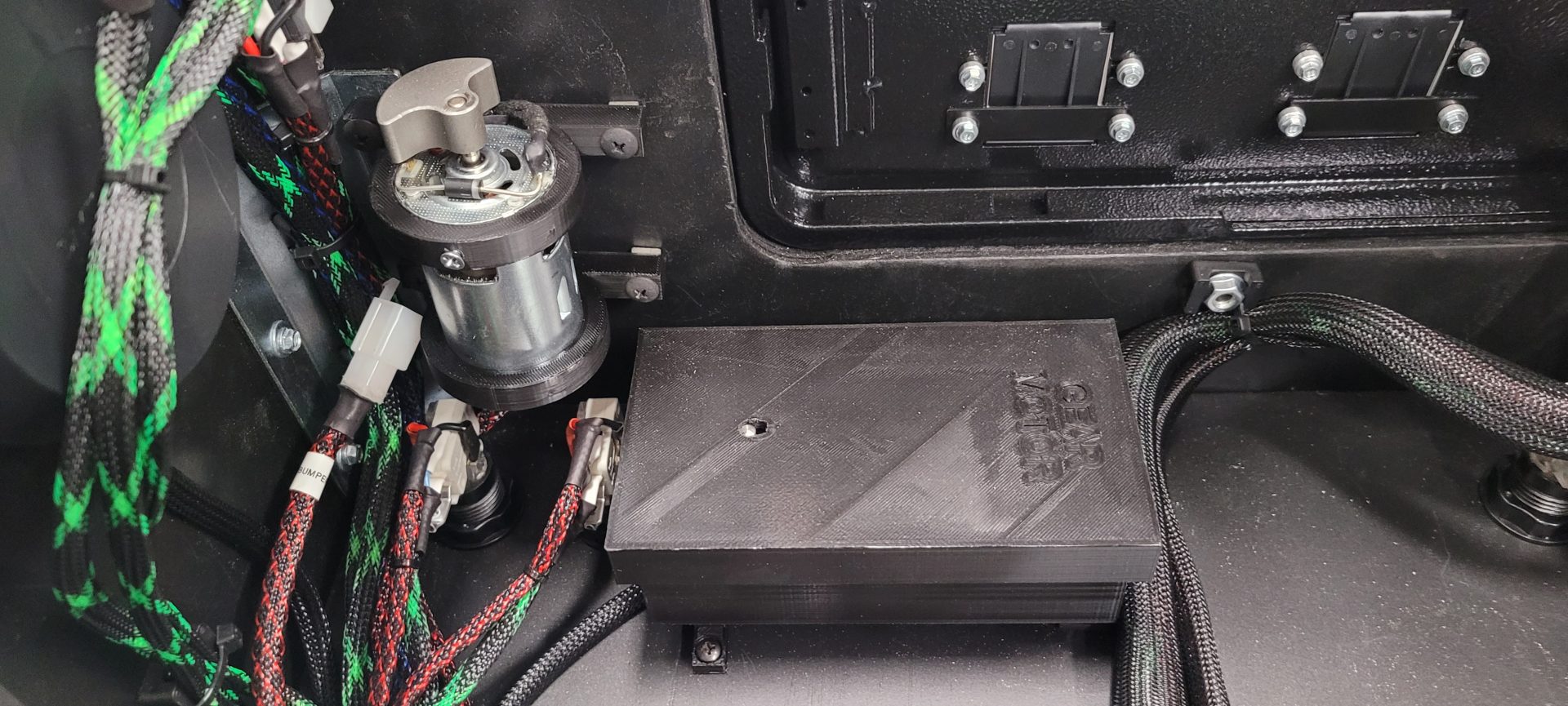
Adding the shaker motor was kind of interesting: the motor itself was a cheapy from Amazon that required a control to slow it down from its standard 8000RPM. The control is what was mounted in the coin door, but the shaker motor itself didn’t come with any mounting hardware at all. I 3D printed a couple mounting rings for the body of the motor:
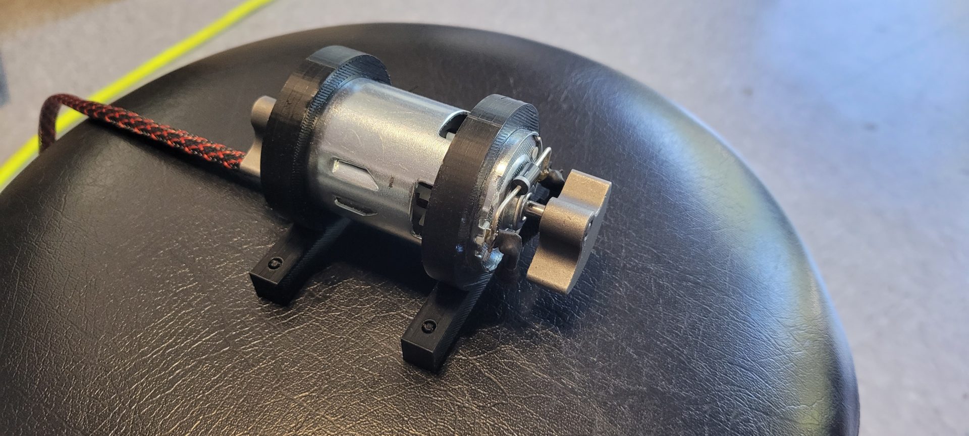
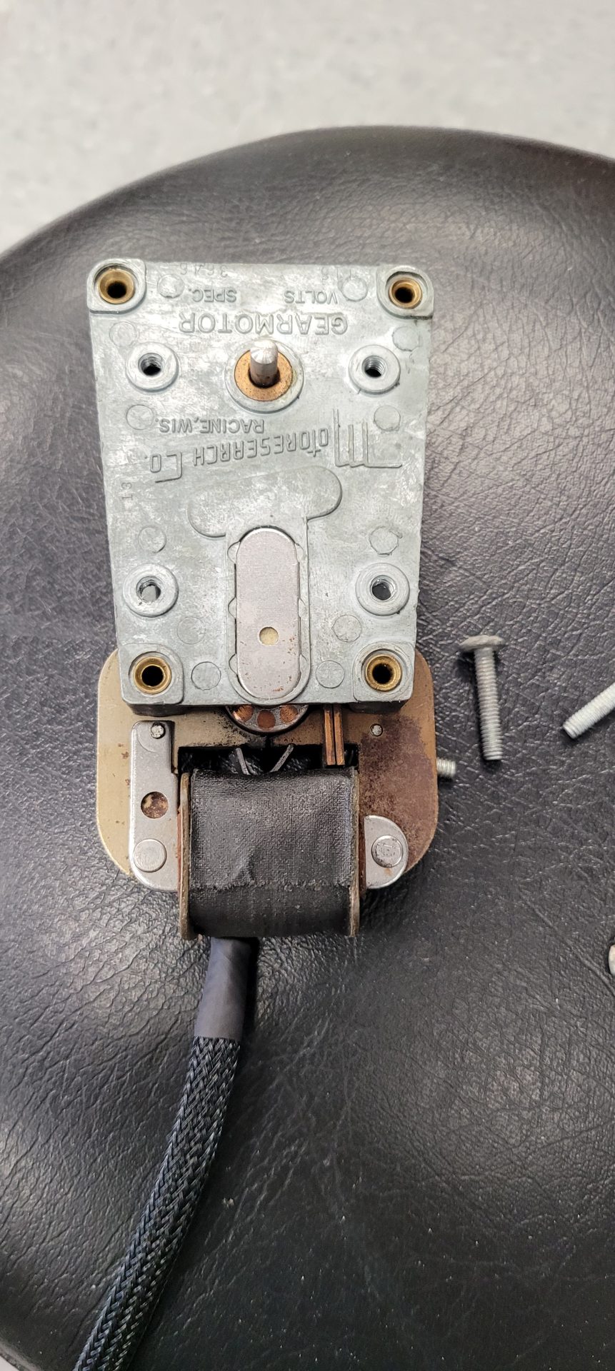
I added a set screw in the upper mount to insure it didn’t work loose and the assembly was fastened to the front wall of the cabinet. Same thing for the gear motor from my Tom Tom – I printed an enclosure for the gear motor and mounted it to the floor below the coin door:
 |
 |
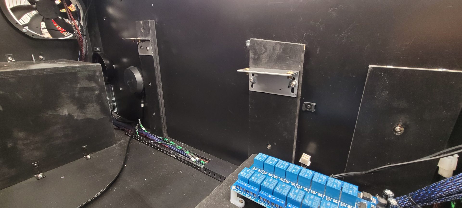
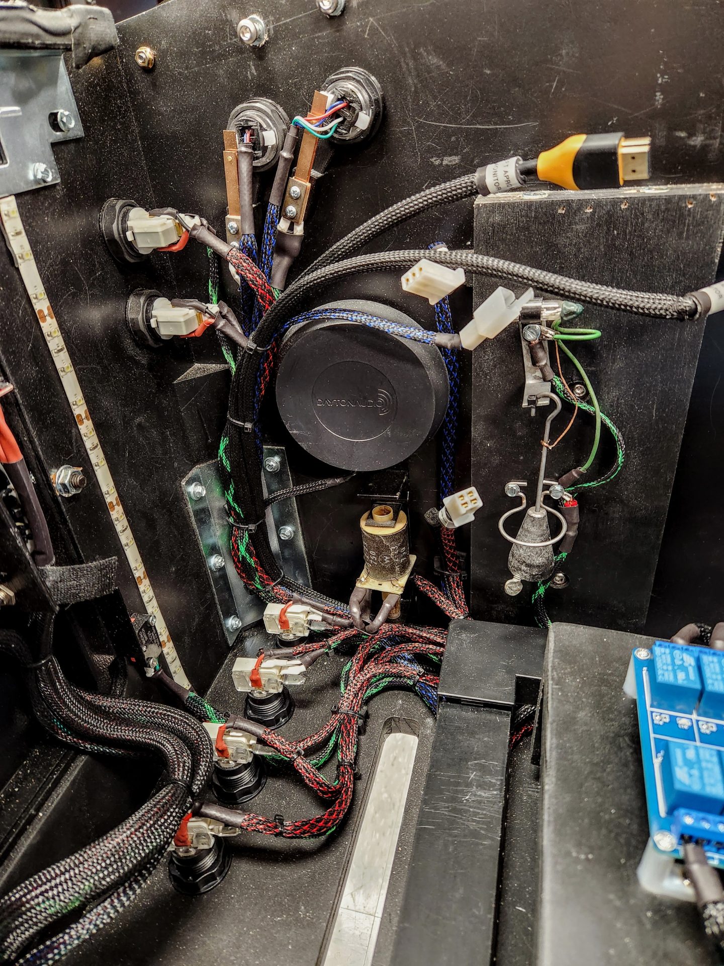
The image below shows the shaker motor to the left and the gear motor on the floor:
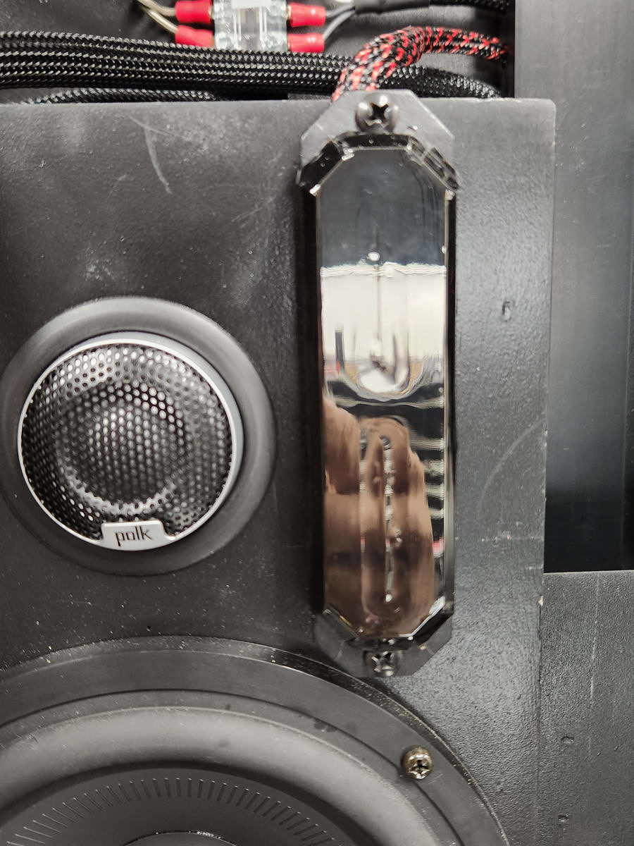
Adding the exciters for SSF sounds was super easy. I used Dayton Audio HDN-8 transducers, which screwed directly into the sides of the cabinet with a single screw and wired to the amplifiers dedicated for their use – more on those later. In the pictures below, the front exciters are on the walls below the flipper buttons and the rear exciters are on the walls on either side of the sub enclosure:
I made a choice at the beginning of the project to use as much used or in-stock gear as I could to try and keep the cost down (which I was semi-successful at :- ). Being in the car audio biz for 46 years meant that I have gathered a ton of old gear, and this project was where some of it could be used. I had two small 1980’s-90’s Alpine car audio amps (3505 and 3006) floating around for 30+ years, sand it would be fun to give them a new lease on life. These amps are capable of 18 wats per channel and would be perfect for the SSF audio. I added a Boss BE1200.4D 4 channel amp (225Wx4) for the main speakers and subwoofer. All of these amps and the 7 channel USB sound card were mounted in the back box:
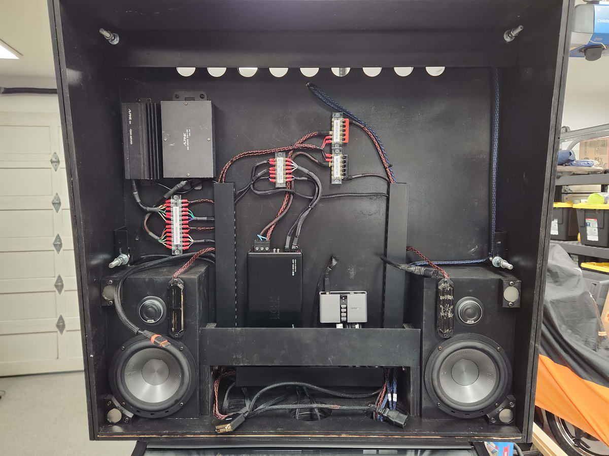
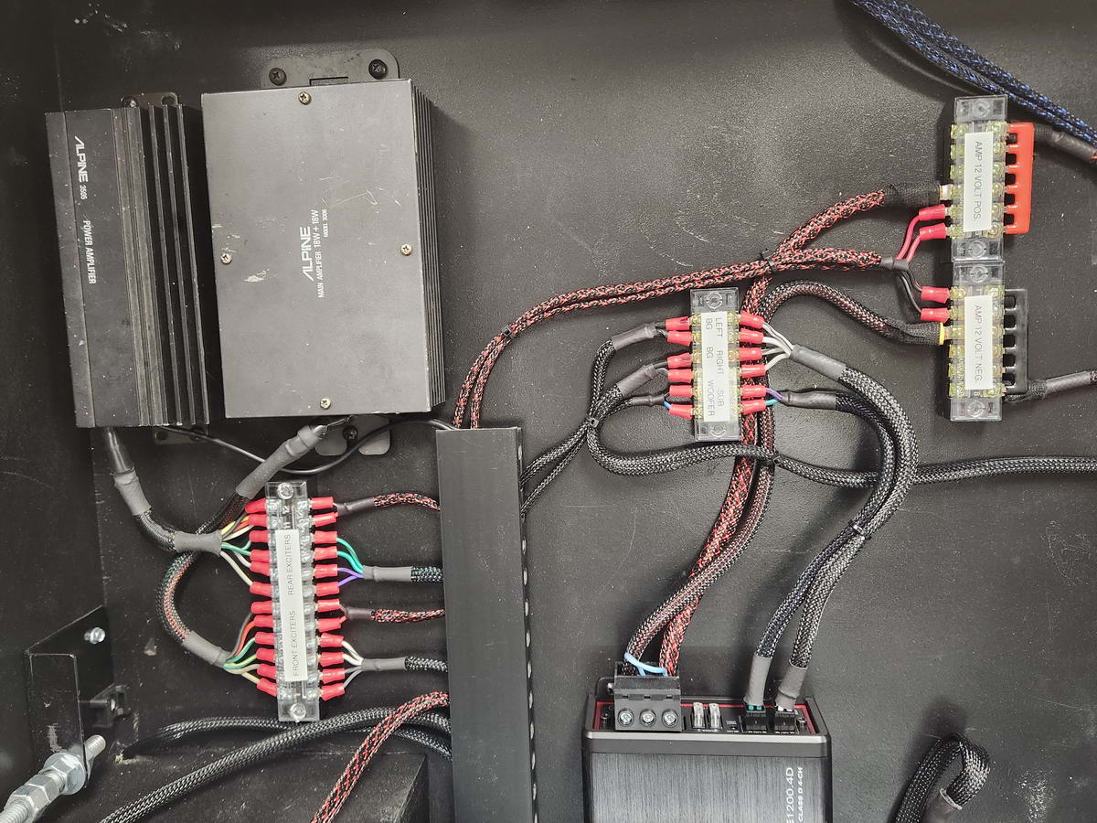
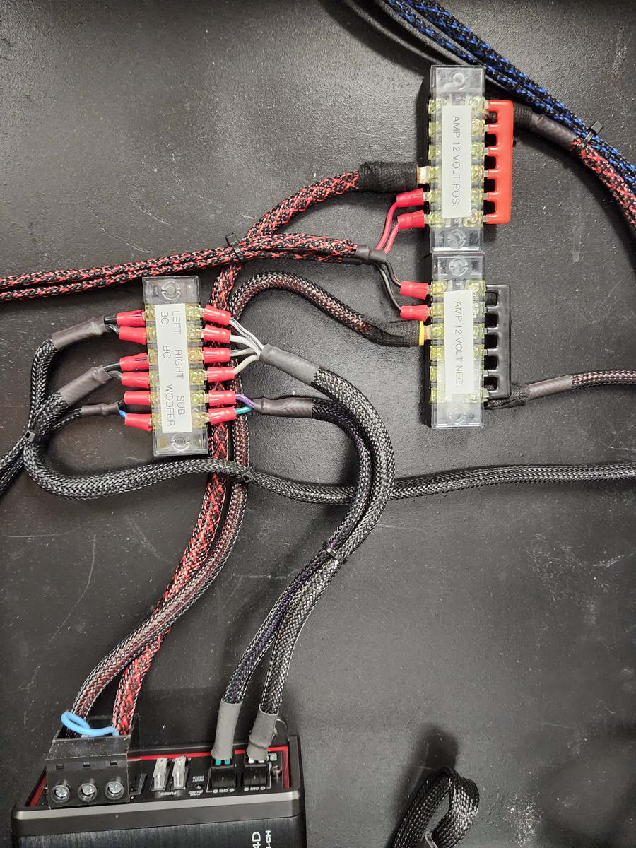
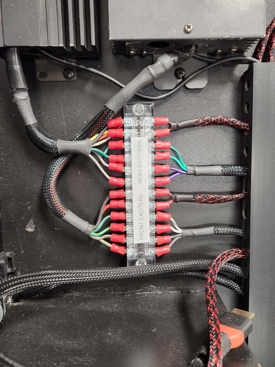
All power and speaker wiring was done with terminal strips and sleeved/heat shrunk, and amp power/ground wiring was done with 10 ga. Each terminal strip was labeled for function :
 |
 |
I had a very large, very capable and very clean 12VDC (15A continuous) ex-display power supply to dedicate to the system, so this provides voltage for the amps and all 12VDC components and is more than enough to handle it all.
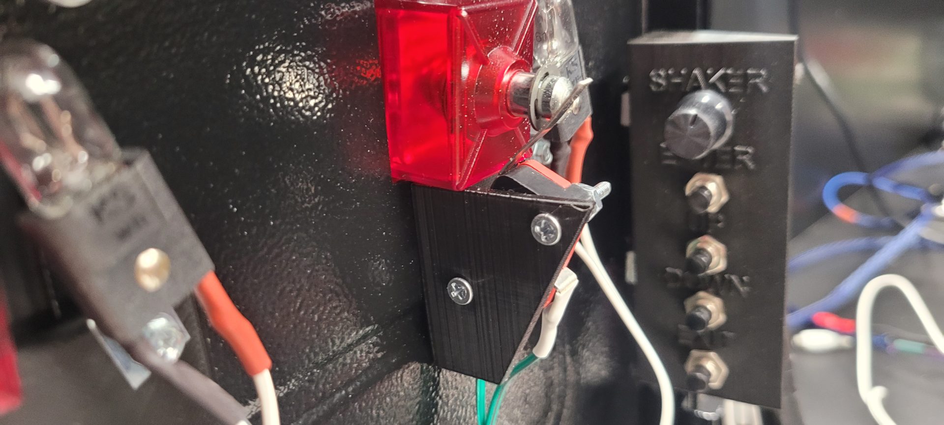
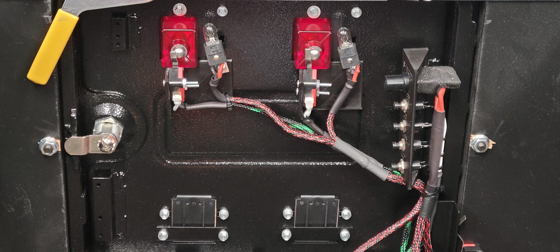
Two white 12VDC 4-LED strobes were mounted next to the main speakers and are visible through the speaker grilles, but they honestly turned out to be WAY too bright at first, so I added two layers of window tint film to them to calm them down a bit, and now they are actually pretty cool:
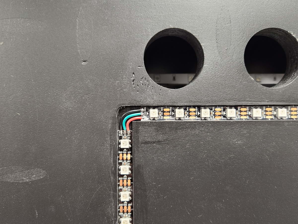
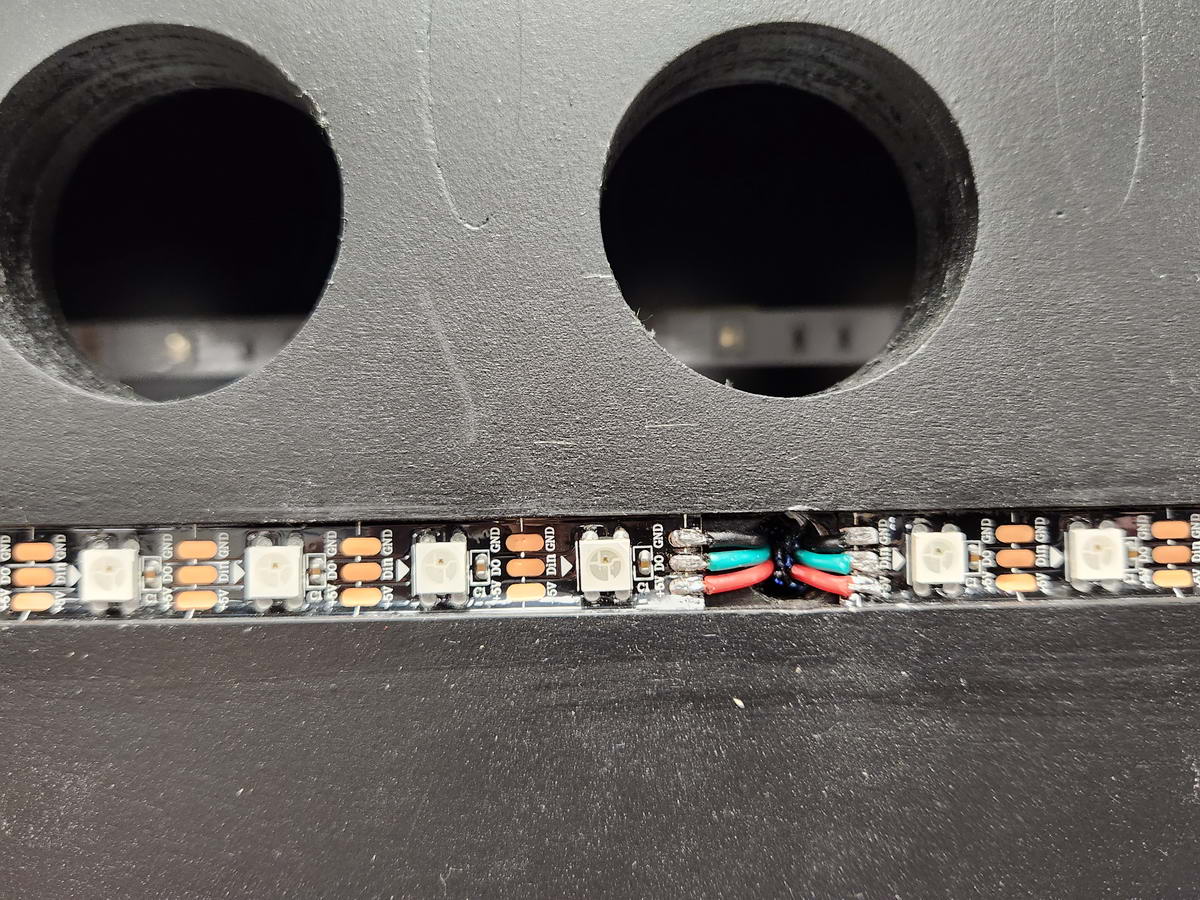
On the back of the back box, I routed a 3/8″ channel for the addressable LED strip to lay in, which actually turned out to be a PERFECT pressure fit as the strip is about 1mm too wide and using a ruler edge, I was able to tap the strip into the channel which pretty much locked it in:
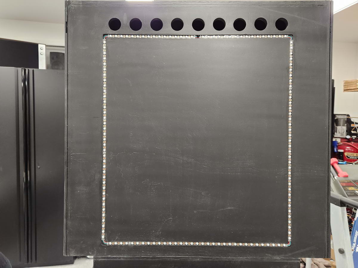
On the corners, I just soldered jumper wires to continue the path to the next strip, and both ends of the strip enter the back box at the top center:
 |
 |
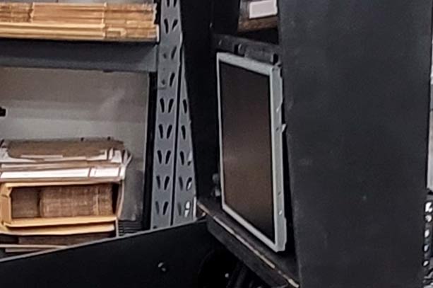
The DMD monitor posed a little bit of a challenge, since it was the old Dell 19″ monitor that lost its mounting points once I removed the case. On the back of this monitor, I added a small portion of a bracket that was designed to have garage cabinets hung from it – basically a flat bar with a angle at the bottom that could hang on any flat angled surface:
I decided to make a cross brace with two legs that would fit between the speaker boxes, with an angled edge at the top to hang the monitor on:
The legs had slots so I could vary the fore-aft dimension and very easily get the DMD monitor to fit flush in the removeable DMD grille panel, and I used 1/4″-20 Allen bolts and the threaded inserts in the sides of the speaker boxes to tighten the assembly:
Once it was hung on the bracket, the DMD monitor was actually very stable because the angle of the bracket on the monitor was less than the angle on the mount, so it ended up being a friction fit that never “bottomed out” so it stays tight at all times:
I wanted the DMD grille to be easily removeable and not have to use a hook or anything like that, so I decided on magnets and Velcro. On the back side of the DMD grille, I routed a small slot and glued some metal strips on either end, then 3-D printed some magnet holders to screw into the back box on the outsides of the speakers:
 |
 |
In between the magnets, I added a small block with one side of a Velcro strip, and added the opposite side of the Velcro strip to the back side of the grille. This system is very solid, as the magnets by themselves held the grille super tight, and the Velcro is there for added insurance.
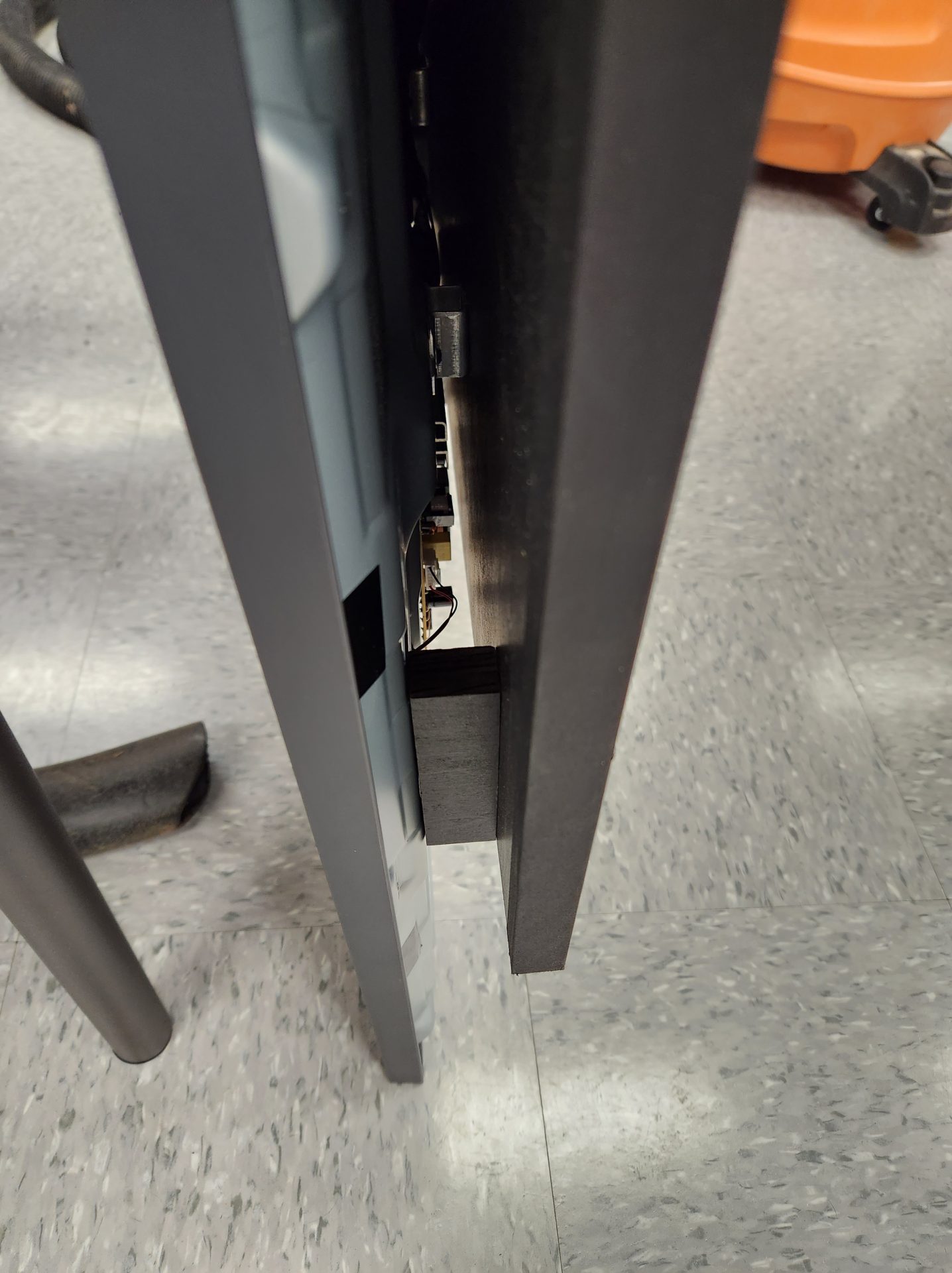
Figuring out how and where to mount the 43″ LG playfield monitor took quite a bit of trial and error. It would need to be mounted with the rear of the screen slightly higher at the rear than the front, giving only the room needed for the LED matrix at the rear, and situated rearward to give room for the two apron monitors at the front. Of course it had to be removeable, and while it was in the cabinet, it had to be able to tilt up and be able to be propped in that tilt position to allow service:
After the rear case of the LG was removed, I sat it in the cabinet on a box to approximate where it would need to be to accommodate the other components, then measured carefully and cut a square piece of plywood and drilled four holes for the VESA mount screws. I attached this to the TV and sat it back in the box to determine where the pivot needed to be. Once that was determined, I cut an old curtain rod slightly shorter than the inside dimension of the cabinet and screwed it to the rear edge of the TV mount:
 |
 |
However, there was a slight issue because the VESA mount is designed to hold the TV vertically, and I was mounting it horizontally (and had de-cased it, removing support), so now the edge of the TV facing the player (bottom of the playfield) was drooping. I added two blocks to the platform to prop up the outer edges of the screen, eliminating the droop:
 |
 |
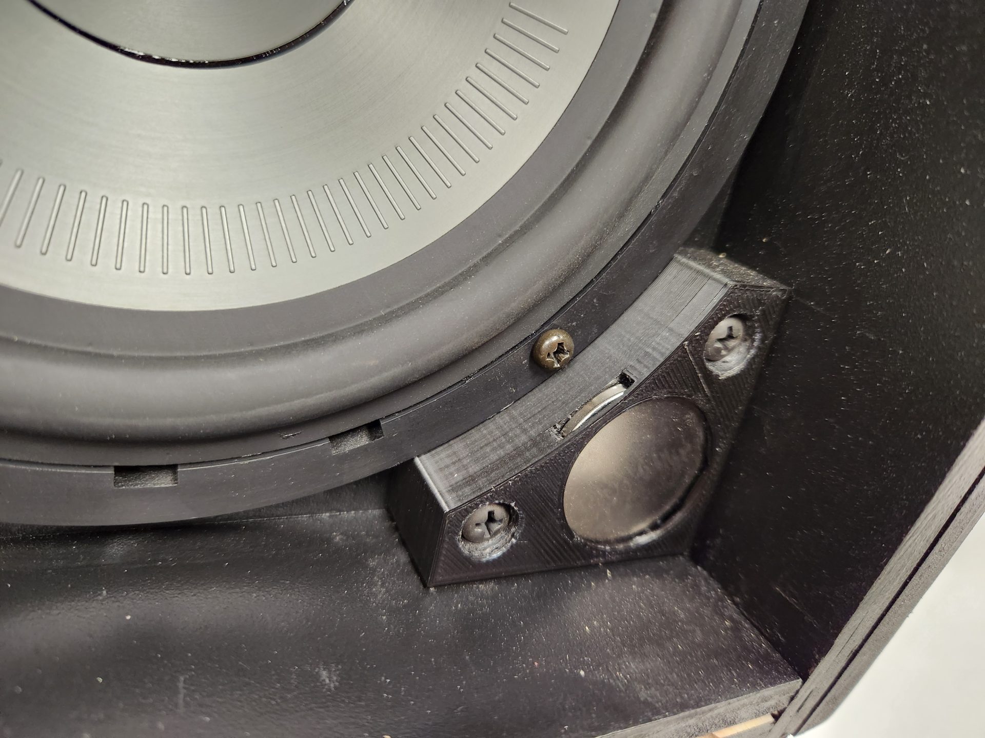
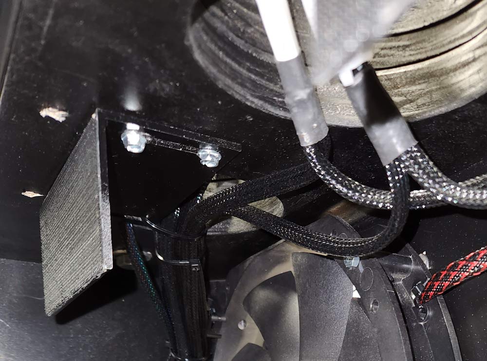
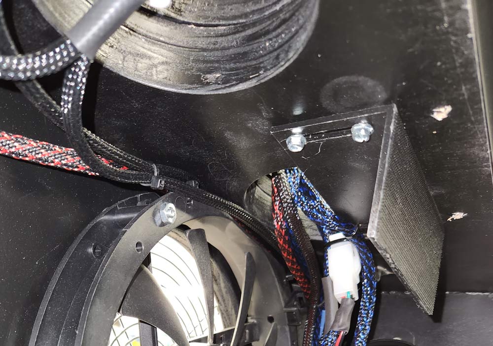
Once this was assembled, I measured and cut four pieces of 3/4″ plywood to form the support for the monitor mount, which would also double as the mounting points for the cross members to hold the flippers/slings/bumpers. On the rear set, I cut a “saddle” for the curtain rod to sit in and form the pivot, and the front set formed the stop for the monitor plate to rest on. These were attached to the side walls of the cabinet with 1/4″-20 Allen bolts and threaded inserts:
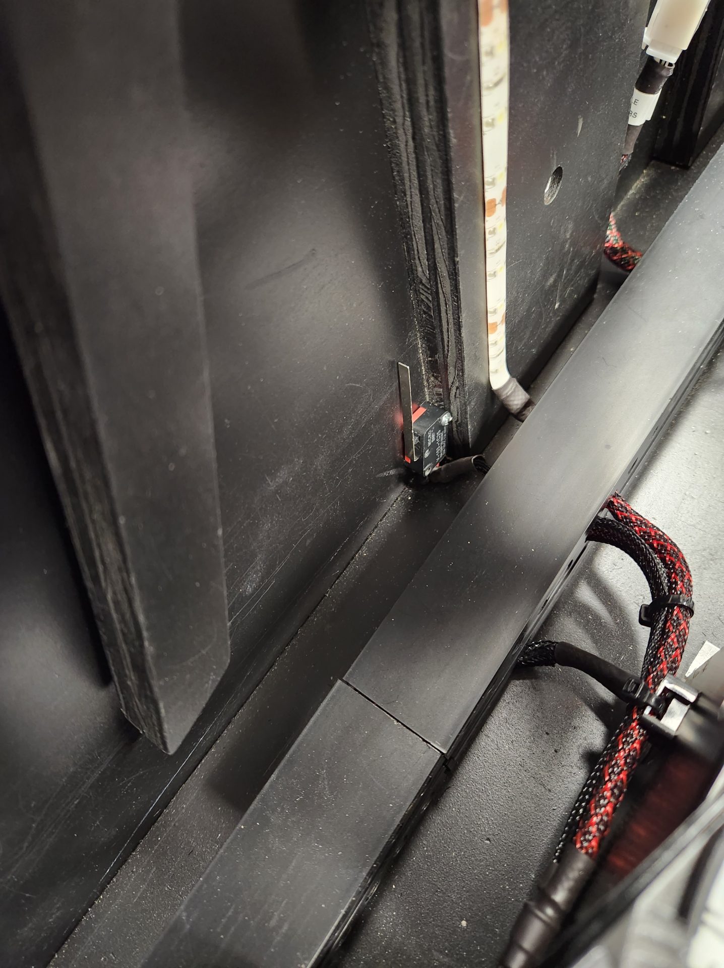
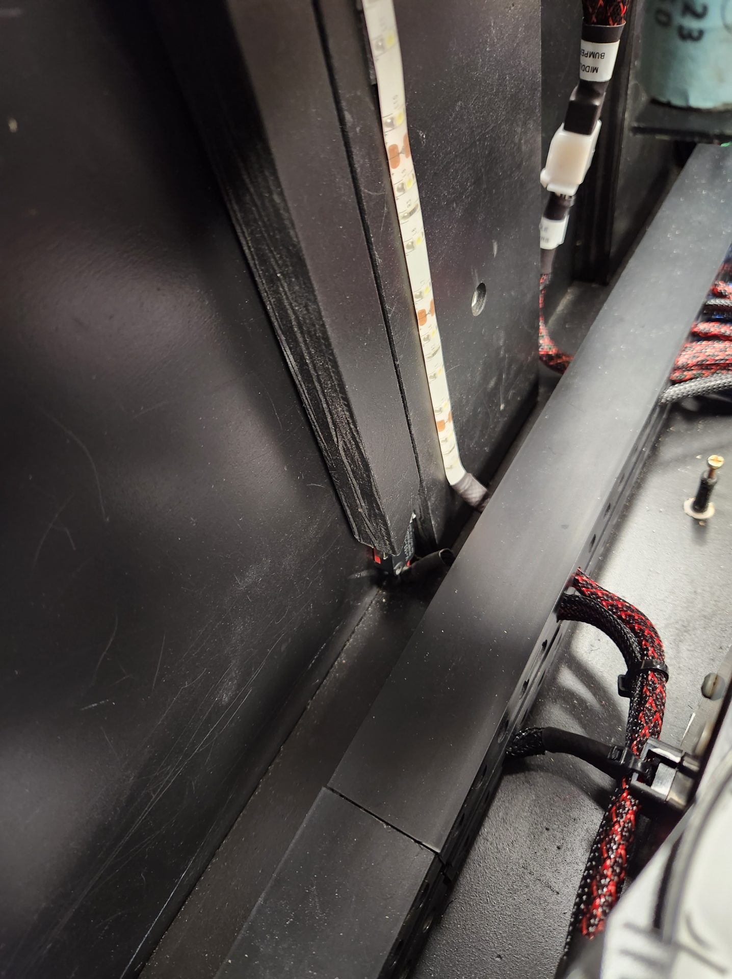
On the right side wall of the cabinet, I added a prop rod for the 43″ TV by drilling for a threaded insert and attaching the prop rod at the top with a 1/4″-20 Allen bolt with red Locitite on it – this allowed me to tighten the bolt to take the slop out of the prop rod, but it won’t loosen the bolt over time. I added a microswitch at the bottom of the prop rod that, when the pro rod is moved up, switches on 12 VDC LED strips in the cabinet for interior lighting::
 |
 |
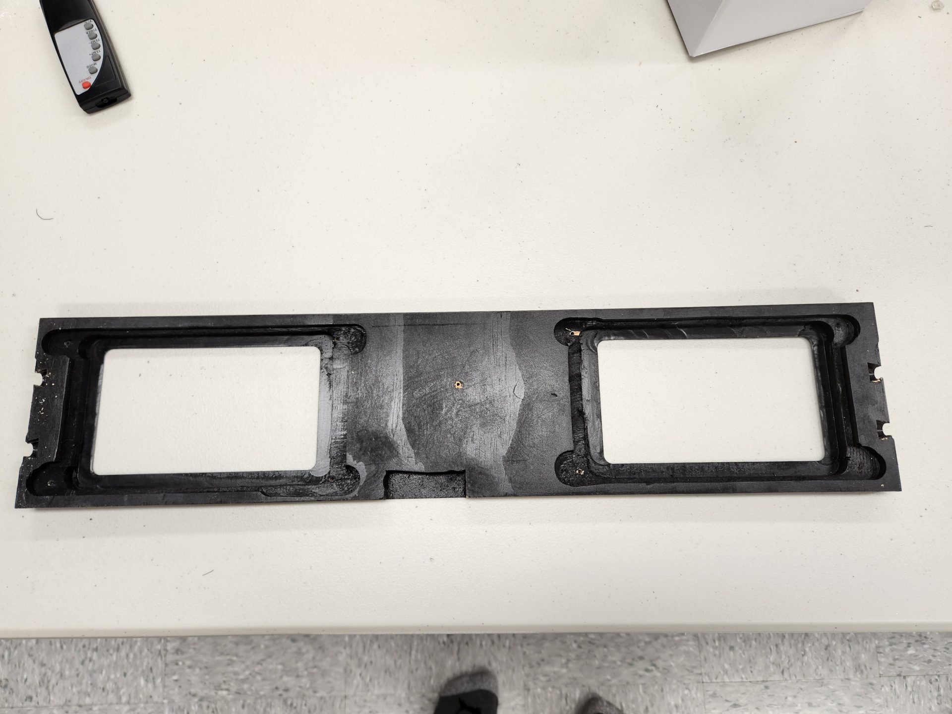
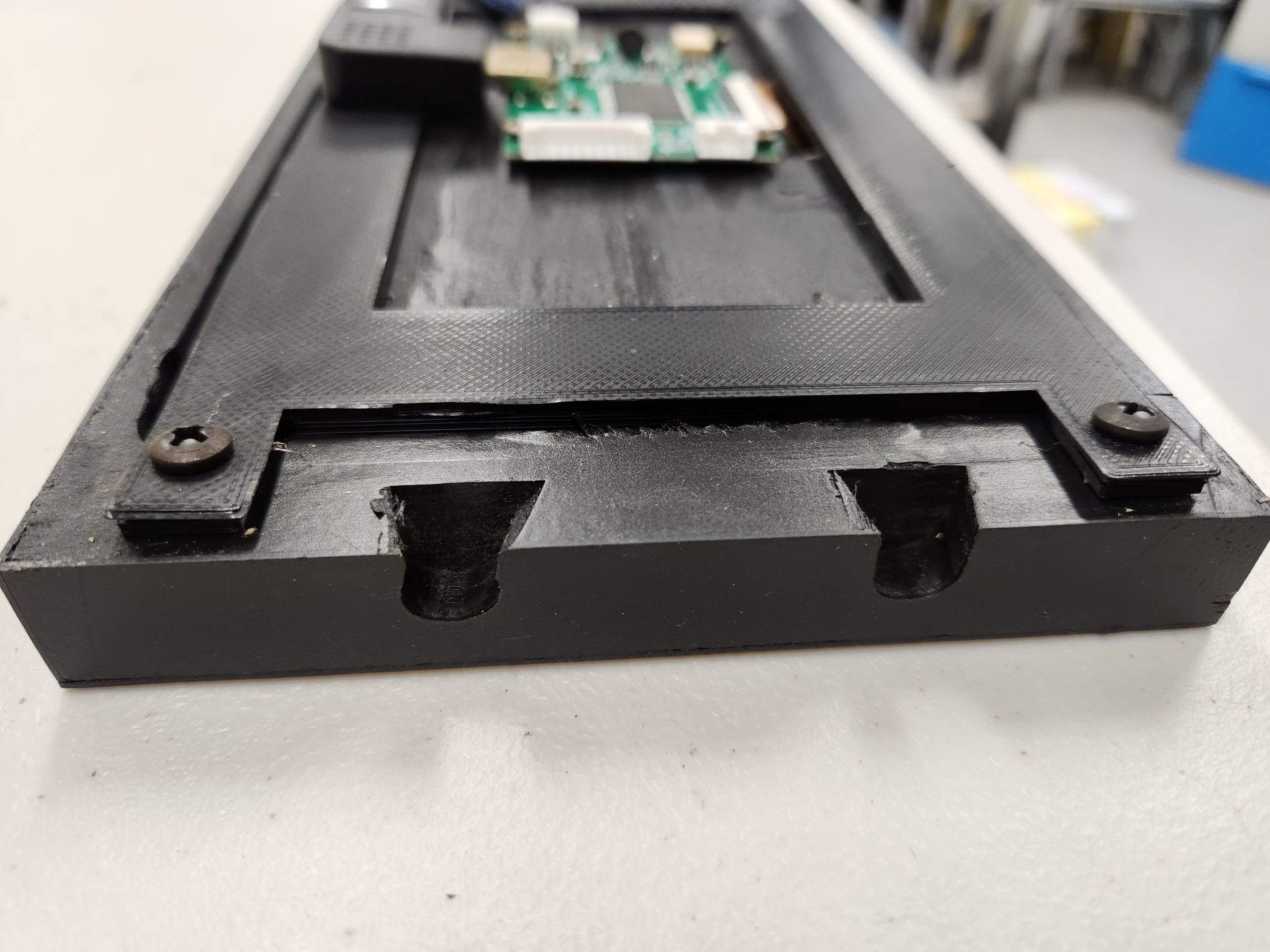
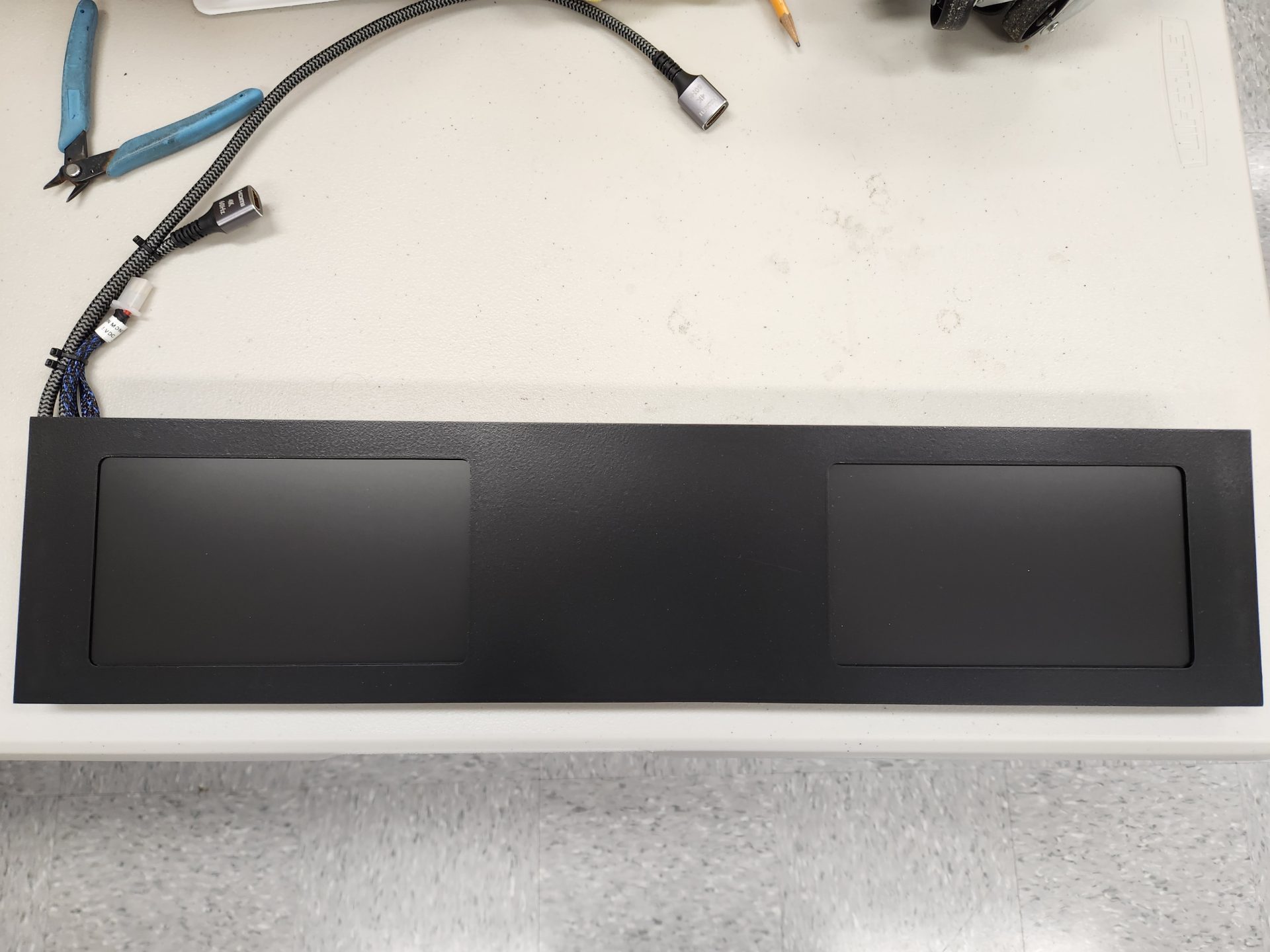
The design of this machine included using two monitors for the apron, to display video, instruction cards, etc. for each game, and I had the Rosen 8″ monitors to use, but the mount needed to be made. This was actually not too hard to do: To begin, I cut a panel of 3/4″ plywood scrap 23 1/2″ x 5 1/4″ that spanned the cabinet. I measured the monitors, then 3D-printed housings to screw them to the back of the mounting panel with. With that done, I measured and cut the holes for the monitors to the exact size (which was about 1/4″ shorter than the actual dimensions of the monitor). Once the holes were cut, I laminated the panel and trimmed out the laminate with a trimmer bit, giving nice rounded corners to the monitor openings. After routing out the back of the panel to allow the monitor to mount flush up against the laminate, it looked like this:
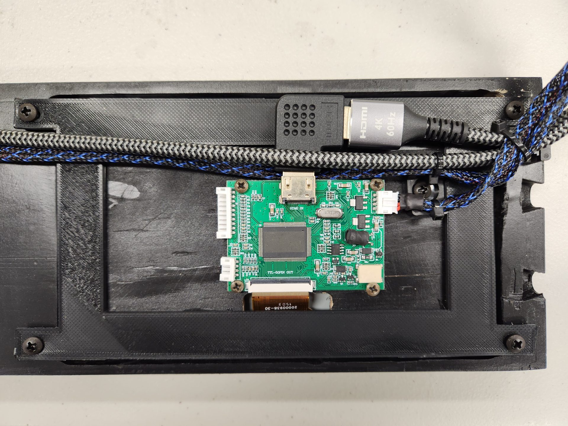
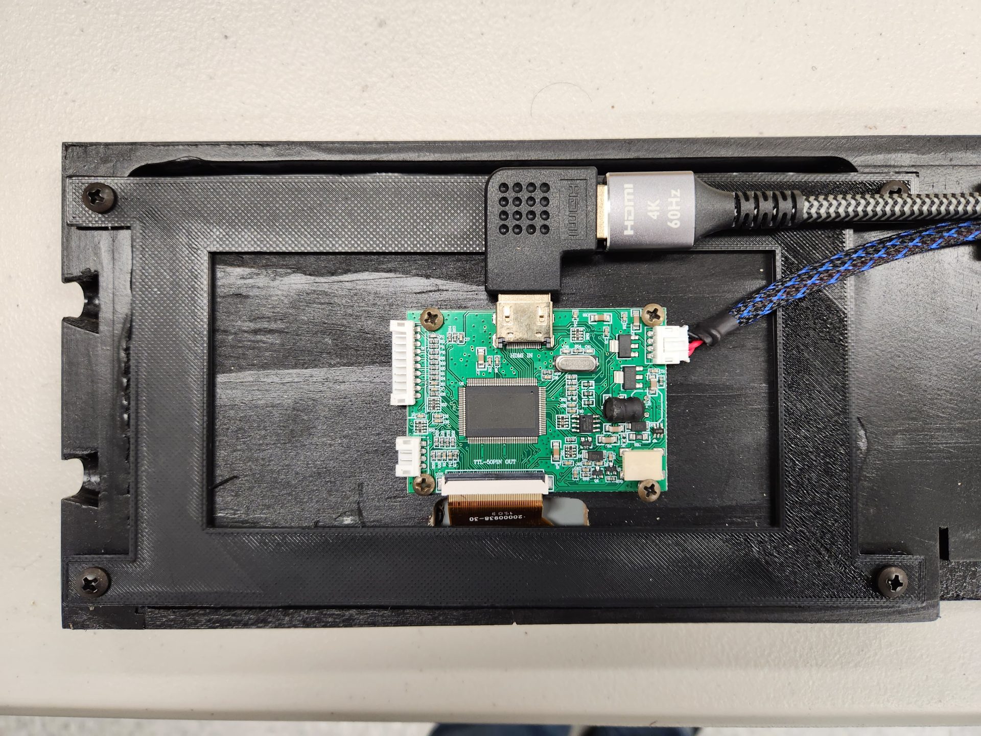
Each monitor required 5 volts and HDMI input, so I sourced some 90 degree HDMI connectors and short HDMI extensions, then made a quick disconnect plug for the 5 VDC connection, making this an easily removeable part:
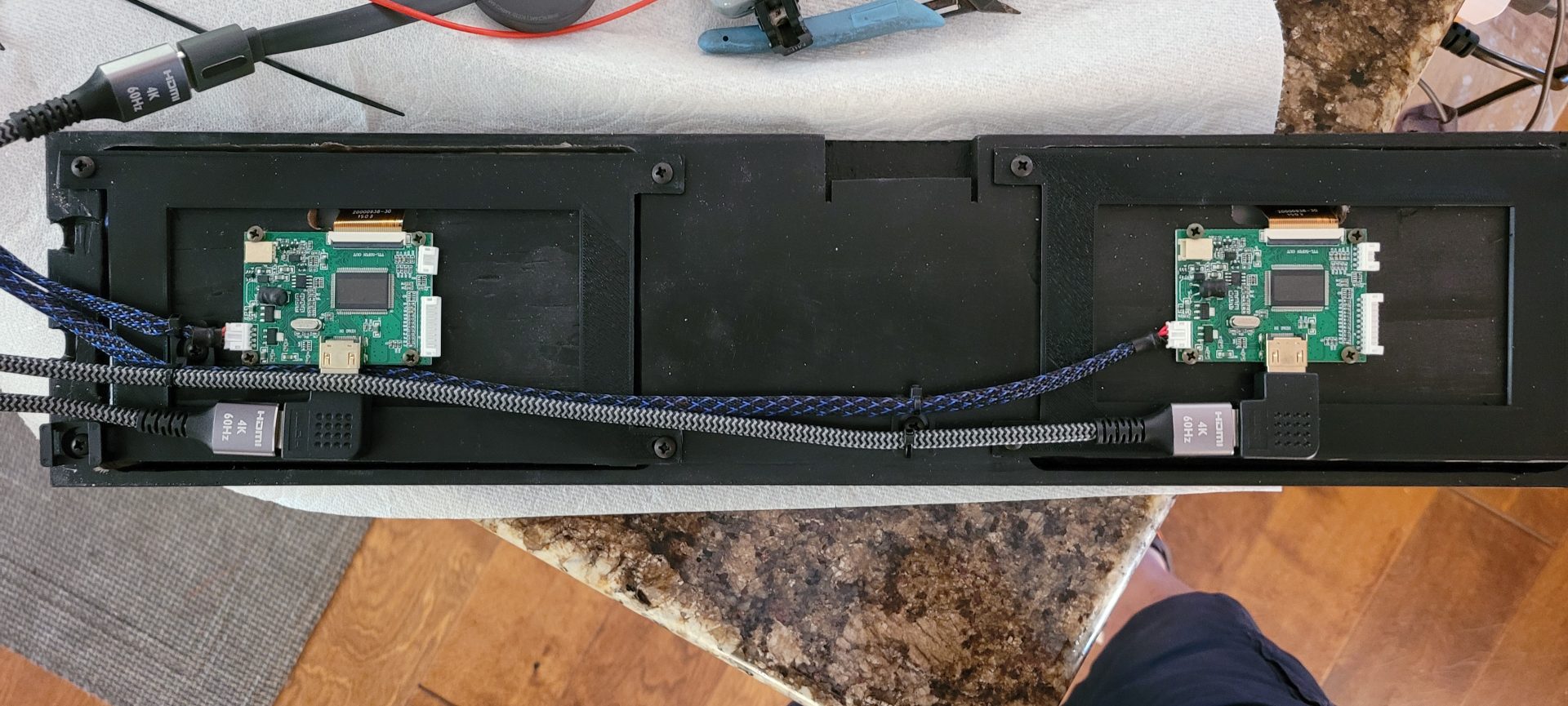
Each monitor had a piece of 1/4″ plywood between it and the 3D-printed bracket to act as a spacer and as a mount for the HDMI board each monitor required:
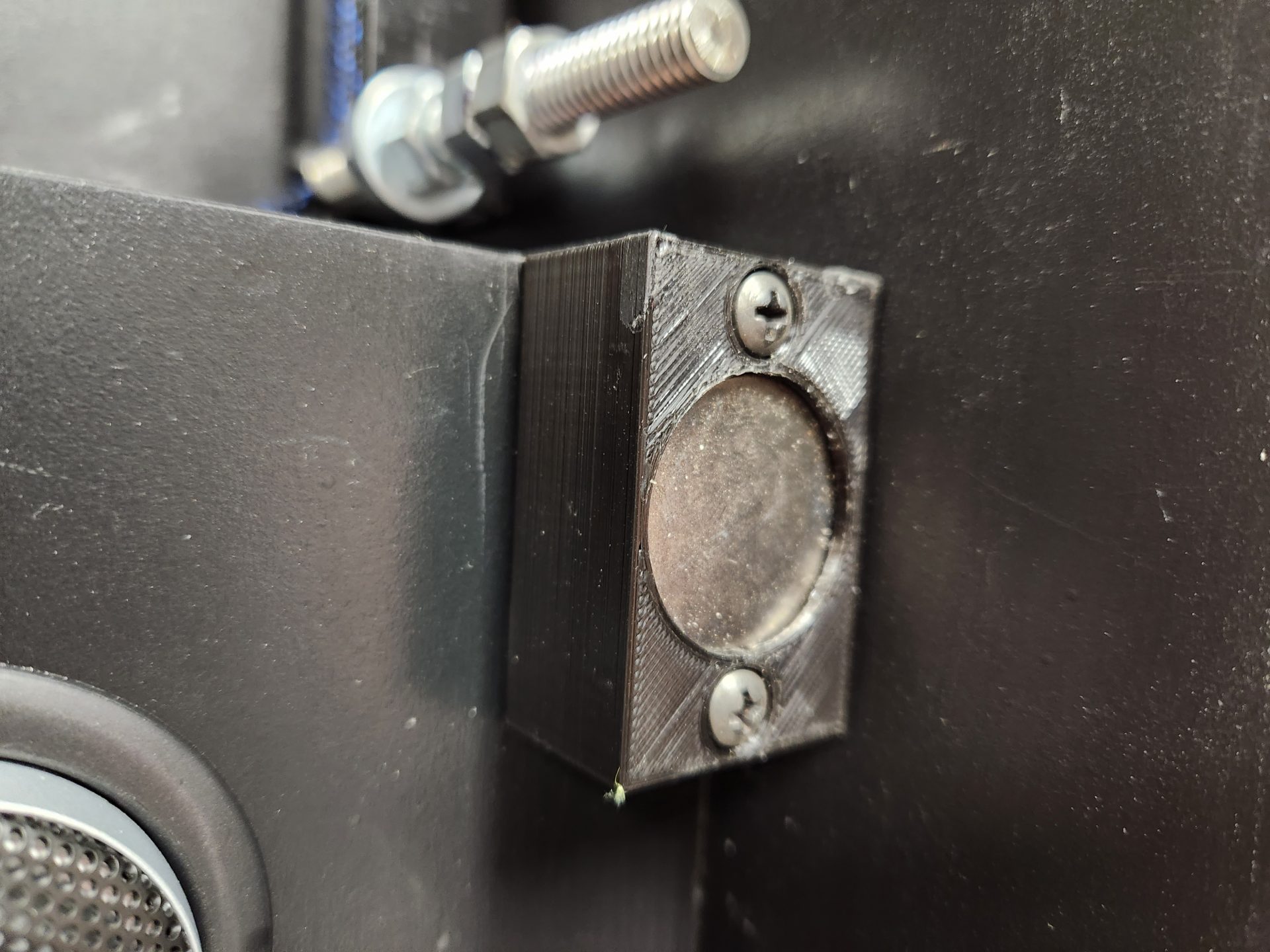
Because there would be no ability to screw this panel in (and I didn’t want to anyway, for ease of service), I had to come up with a way to attach it to the cabinet. I considered velcro, magnets and other types of fasteners, but eventually opted for threaded inserts with 1/4″-20 Allen bolts screwed into the sides of the cabinet, engaging dovetail slots cut in the ends of the monitor panel. This allowed me to vary the depth of the bolt in the side panel to make a “friction fit” on the panel as it lowered onto the heads of the bolts.
The two bolts in the side panel are shown at the upper edge of this photo:
These engage in the dovetail slots in the end of the monitor panel, and the tension on the mount is varied by the depth of the bolt in the hole – when the bolts are all at the proper depth, the panel literally just “snicks” into place and is aligned perfectly, as the depth of the panel is governed by the bolts:
When the panel is removed, it comes out with the two HDMI female inputs and the 5 VDC plug:
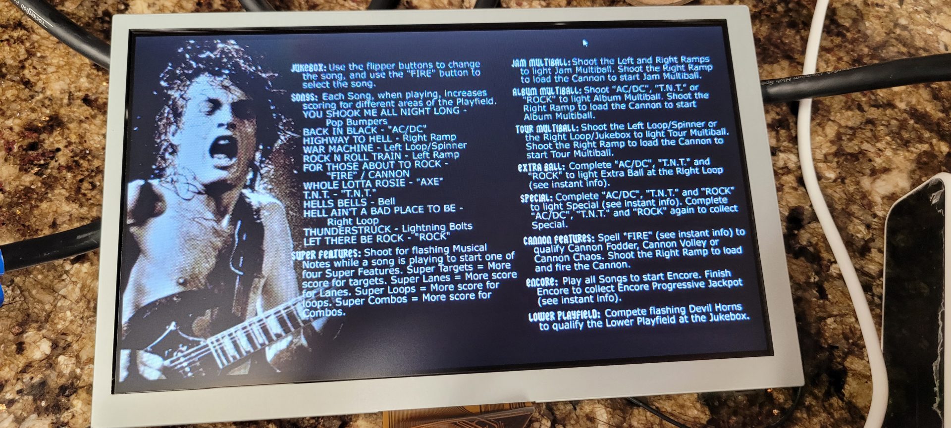
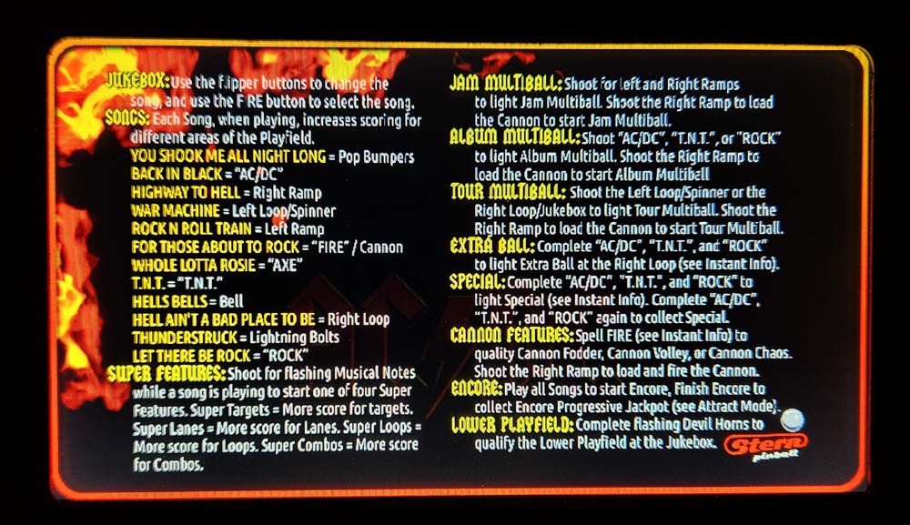
The monitors are decent enough resolution (800 x 480) that everything I have displayed on them is legible and looks great:

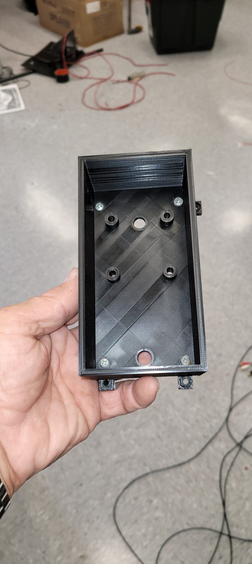
By this time, wiring was piling up and I needed to start organizing things for the Teensy, LED Wiz, SainSmarts and the expansion board for the Zebs Boards Plunger. I knew all of these components were going to be located right behind the coin door, and space was going to be at a premium on the floor of the cabinet, so I decided to make a riser for the modules to mount on that would hide the wiring below, making a much cleaner presentation.
To do this, I built a panel the riser with walls on two sides, with notches cut out of them to allow wiring to pass into the space under the panel. On the bottom of the walls, I drilled 1/4″ holes to accommodate the cam lock posts I installed into the floor of the cab to lock this part down:
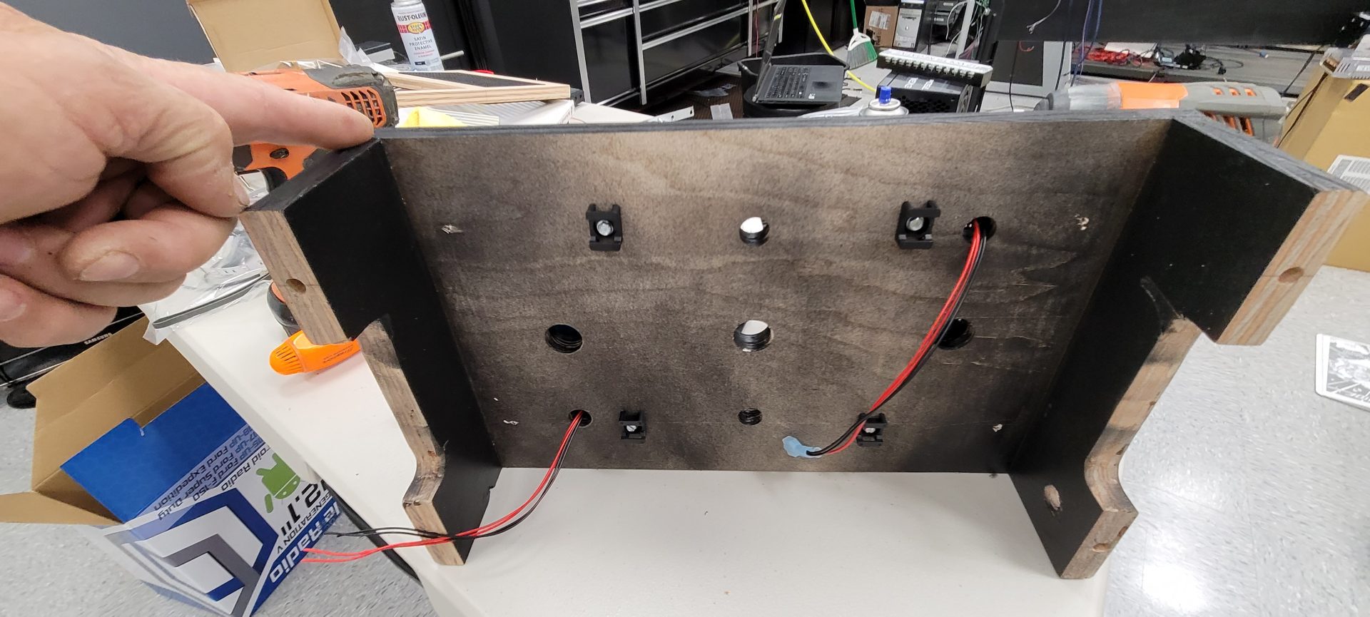
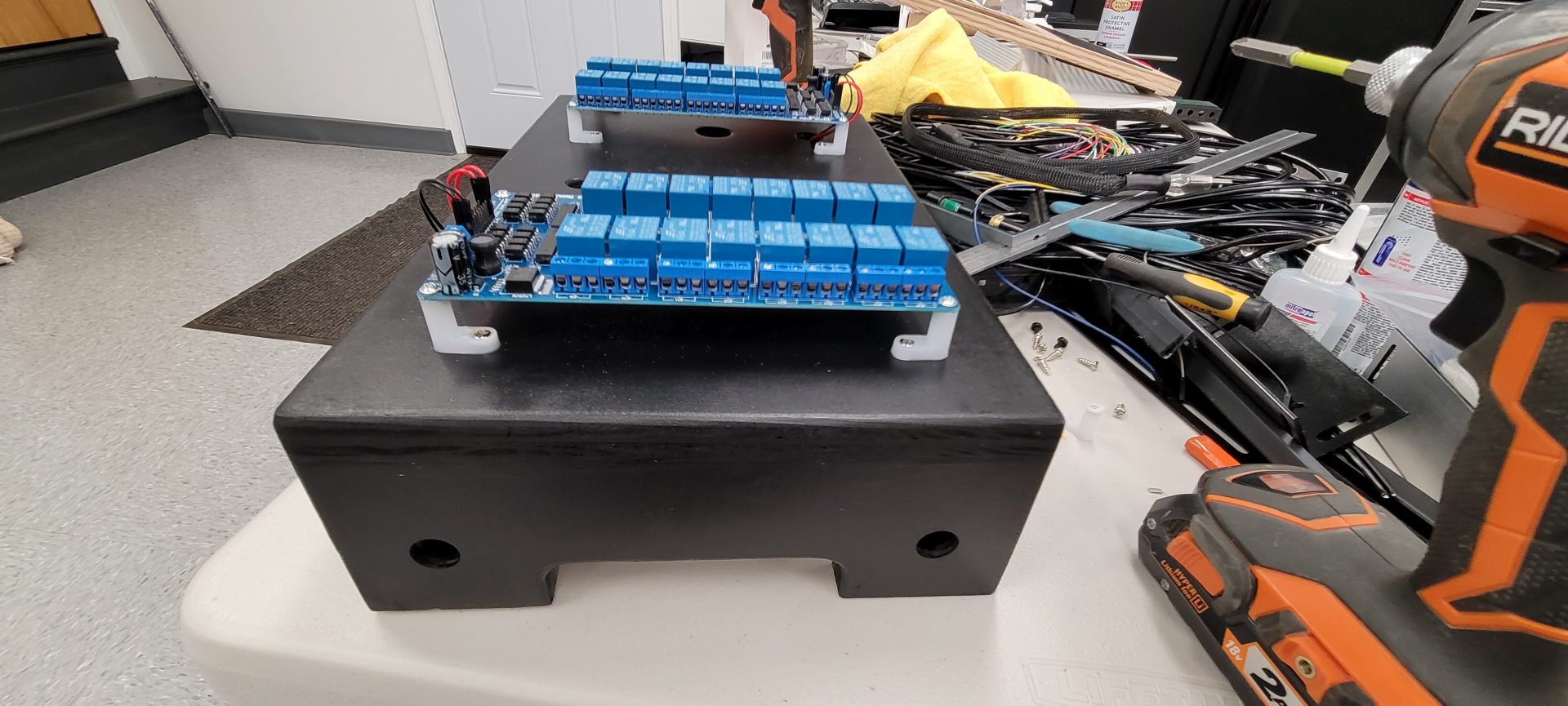
In the top of this panel, I drilled multiple holes to allow the wiring for the LED Wiz and SainSmart boards to come up from the bottom, but all of the holes were located under the modules, so once done, there would be no exposed wires visible, you would only see the ends actually attached to the individual modules:
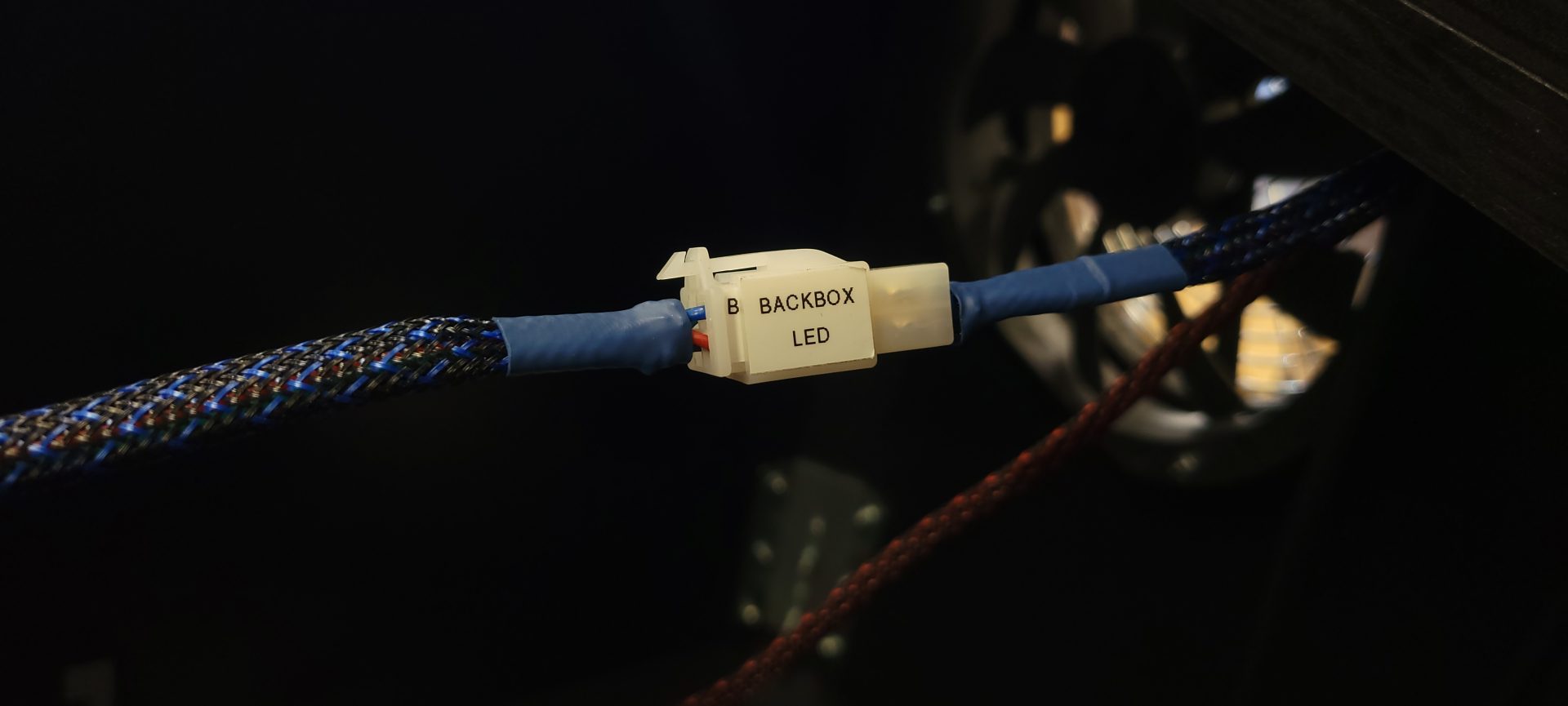
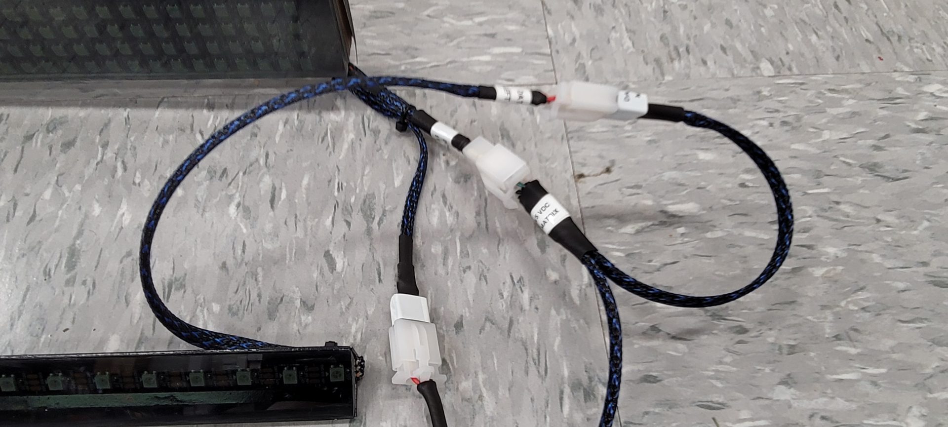
All parts of this build, from the flipper/bumpers to the LEDs and speakers were wired with quick-disconnect plugs that I made using this kit. With these plugs, I was able to use a variety of different male/female sets to insure that each component could only plug into the correct place in the cabinet. These things make life SO MUCH EASIER that I would never attempt another build without using them for all serviceable parts. Not only are they nice for connecting things, but you can label them to make deciphering your wiring much easier:
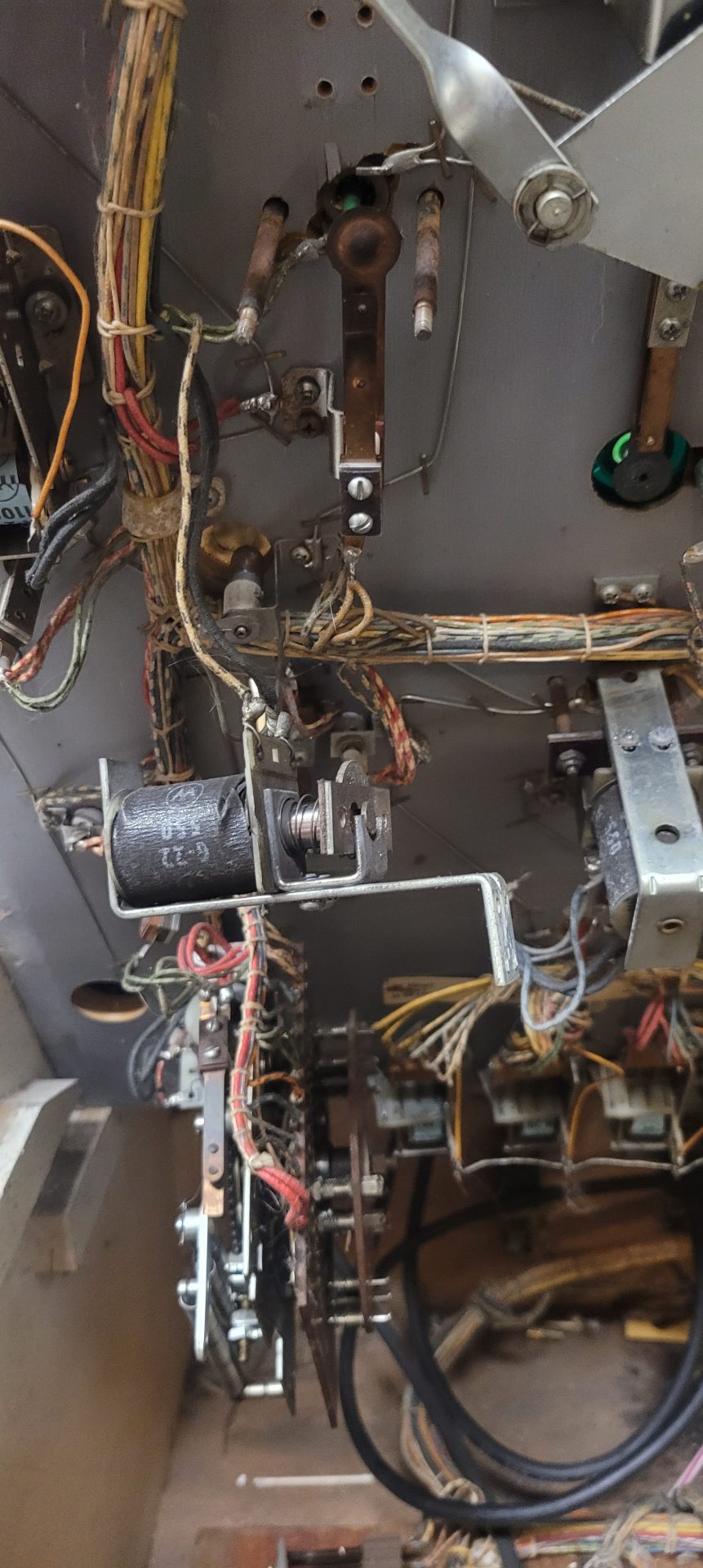
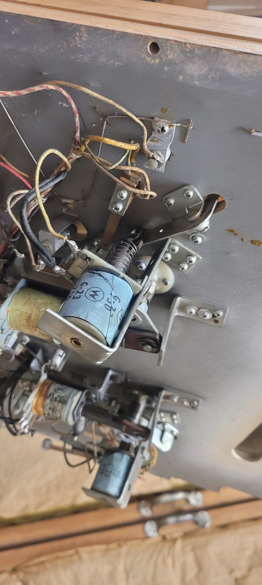
One of the biggest challenges of the build was adding all of the components from Tom Tom. Because Tom Tom was produced in 1963, every part salvaged form the machine was now almost 60 years old:
 |
 |
 |
Because of this, I wanted to make service as simple as possible, with every component to essentially be a “cassette”, where I would mount three or four components to a board, make the board itself easily removeable, and do all wiring with quick disconnects. This would allow not only easy service, but since I could build each component part on the bench prior to adding it to the machine, it made the build process MUCH simpler, both in terms of ease of access, but also easier on my body since I wouldn’t have to be hunched over the machine doing all of the mounting and wiring.
The 10 bumper layout went like this – from the front (coin door) to the rear (back glass):
- (2) Flippers and (2) front slingshots
- (2) Rear slingshots and (1) pop bumper
- (3) Pop bumpers
Since I had laid out all of the components and tested them with the LED Wiz and SainSmart boards in the beginning, I knew that everything worked and could be used. However, I had still not firmly decided on using 24VDC or 12VDC for all the components. I knew the flippers were definitely going to be 24VDC, but I was kind of undecided on the rest of the bumpers and slings. They would need to be installed to see what kind of response they gave before I would make the final decision – more on this later.
BTW: this is a good time to rave about one of the tools I bought for this project, that turned out to be the best thing ever – a 0-30VDC power supply. This thing saved my ass literally hundreds of times on this project, simply because I could test every component without having to rig up individual power supplies – just turn the knob and you get the right voltage and can limit amperage as well – it was a godsend!
Anyway, I started this phase by cutting boards that would span between the monitor mounts on the sidewalls (middle and rear) and a dedicated mount for the front set (flippers and slings). The middle and rear set would mount to some aluminum brackets that were mounted to the sidewalls with 1/4″-20 bolts and threaded inserts, and on the aluminum brackets themselves, I added 1/4″-20 “nutserts” to allow the assemblies to be easily removed:
I disassembled all of the Tom Tom hardware and painted the brackets, cleaned all of the guides and rods, added 1N4007 diodes across the + & – terminals (odd they didn’t have them from the factory) and made sure that everything was working properly and not hanging up etc.
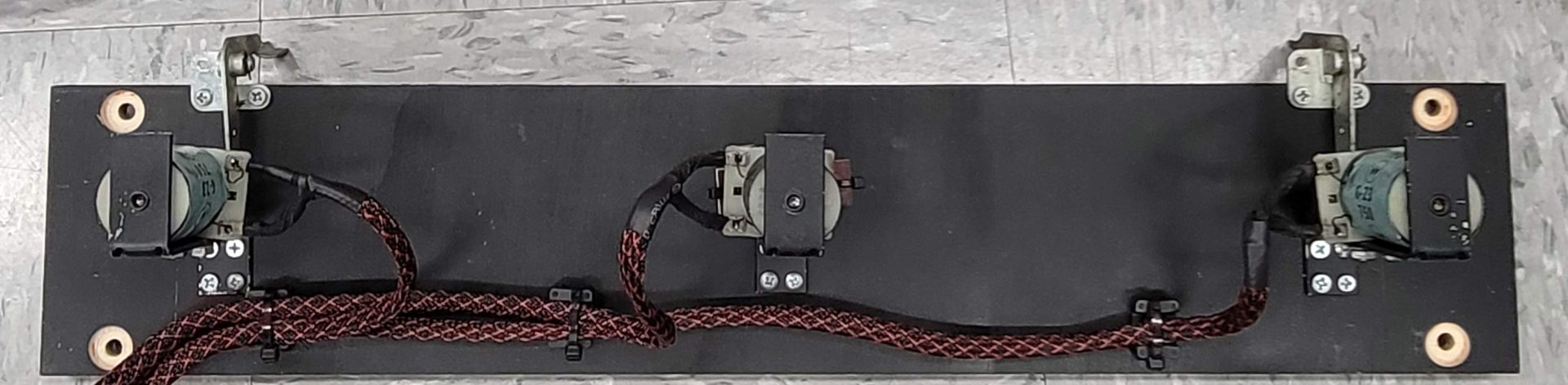
On the pop bumpers, I removed the actual bumper/spoon assembly and just zip-tied the plates together, then mounted the brackets to the boards, and soldered and sleeved/heatshrinked every wire and mounted three bumpers to the rear board:
On the middle board, I added one bumper in the middle and two slingshots to the outsides. Although the slingshots could have been run simply as solenoids banging against wood, I decided to keep the actual metal arms that formed the slingshot portion and mounted them towards the edge of the board so the slingshots when triggered hit the edge of the board as a stop:
Note that each board had the holes countersunk on the back side to clear the nutsert on the top of the mounting brackets.
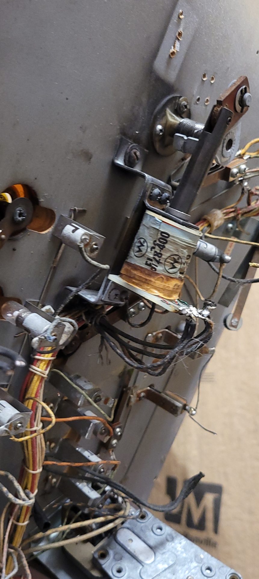
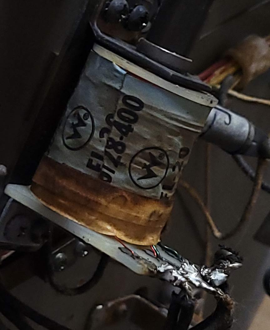
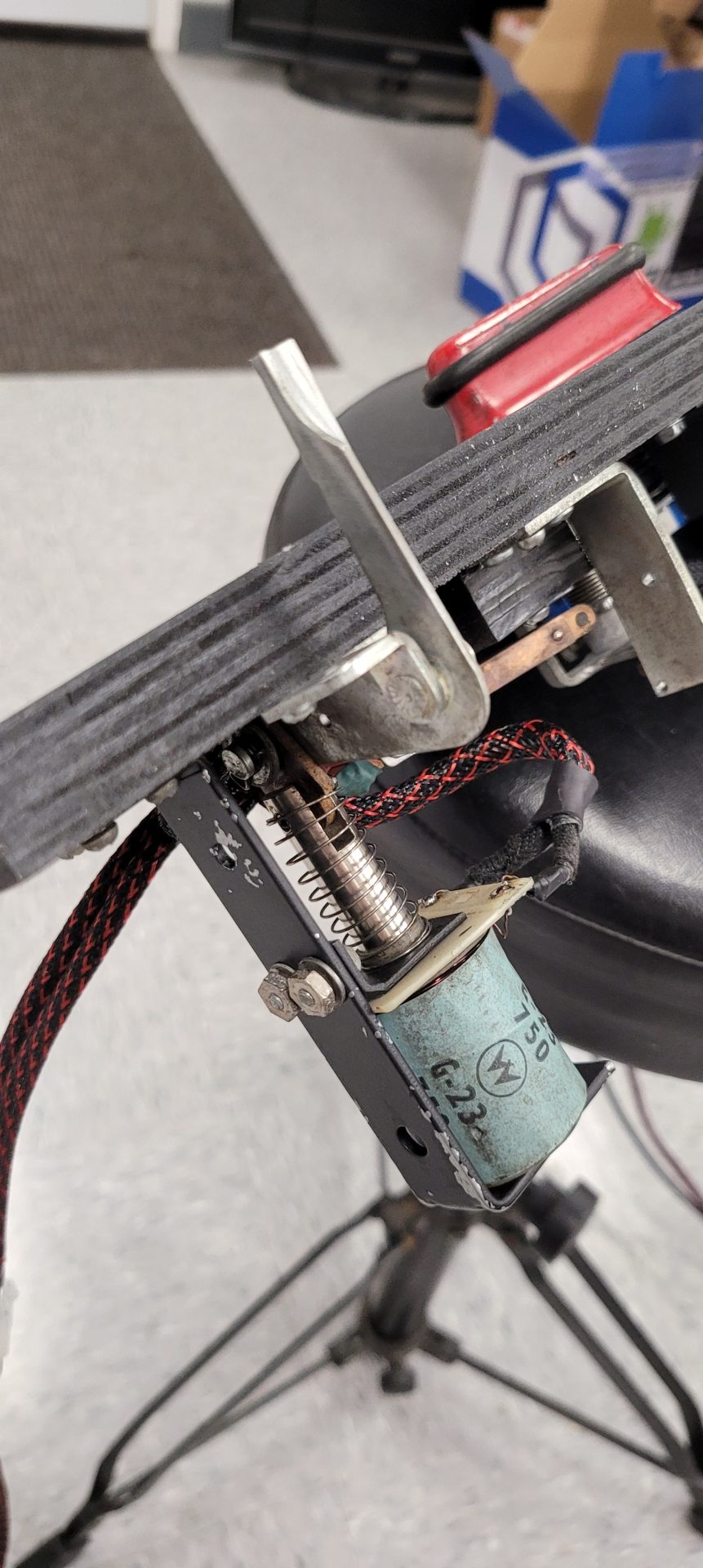
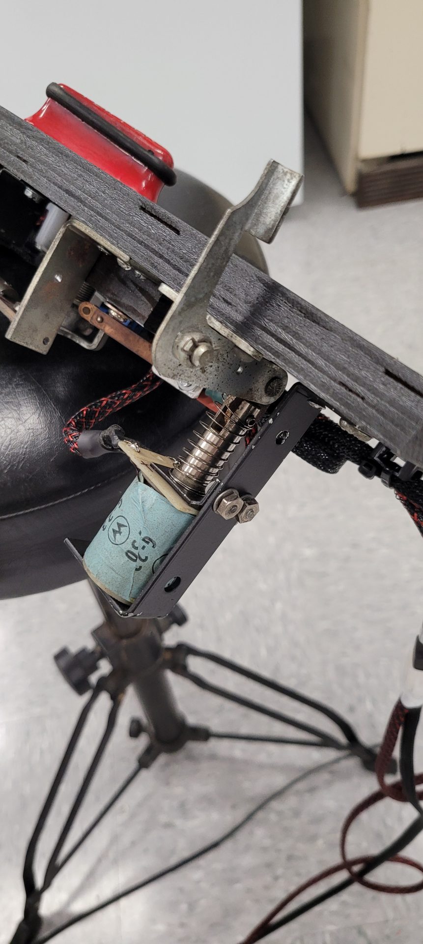
The flipper assembly was DEFINITELY the hardest of the three modules to build, mainly due to the flippers requiring dual voltages to run each flipper. By dual voltage, I mean that each flipper was designed to run on (I believe) 40 VDC in the game to give you power on flipper actuation (GREEN wires in the coil photo below). However, if you hold the flipper on for any length of time, the coil begins to heat RAPIDLY. In my case, running 24VDC heated up the coils to the point I couldn’t hold them in about 30 seconds. Obviously, this was not going to work long-term. What was nice about these coils though is that they have a second coil designed to be powered by a MUCH lower voltage, powered on when the flipper reaches the end of its stroke (RED wires in the photo below). This power transfer is handled by an EOS (end of stroke) leaf switch. Read more about EOS operation.
To build the flipper “module” I needed to provide not only 24VDC to the flippers but that lower voltage to hold them open. With my variable power supply, I determined that when the flippers powered on with 24VDC, they drew about 8 amps each – almost 400W of power! However, when I enabled the hold coil and set up the EOS switches, they only needed a little over 1.5 VDC to hold them open, with negligible amperage draw, meaning I could trigger the flippers and hold them on almost indefinitely – they would be in no danger of burning up.
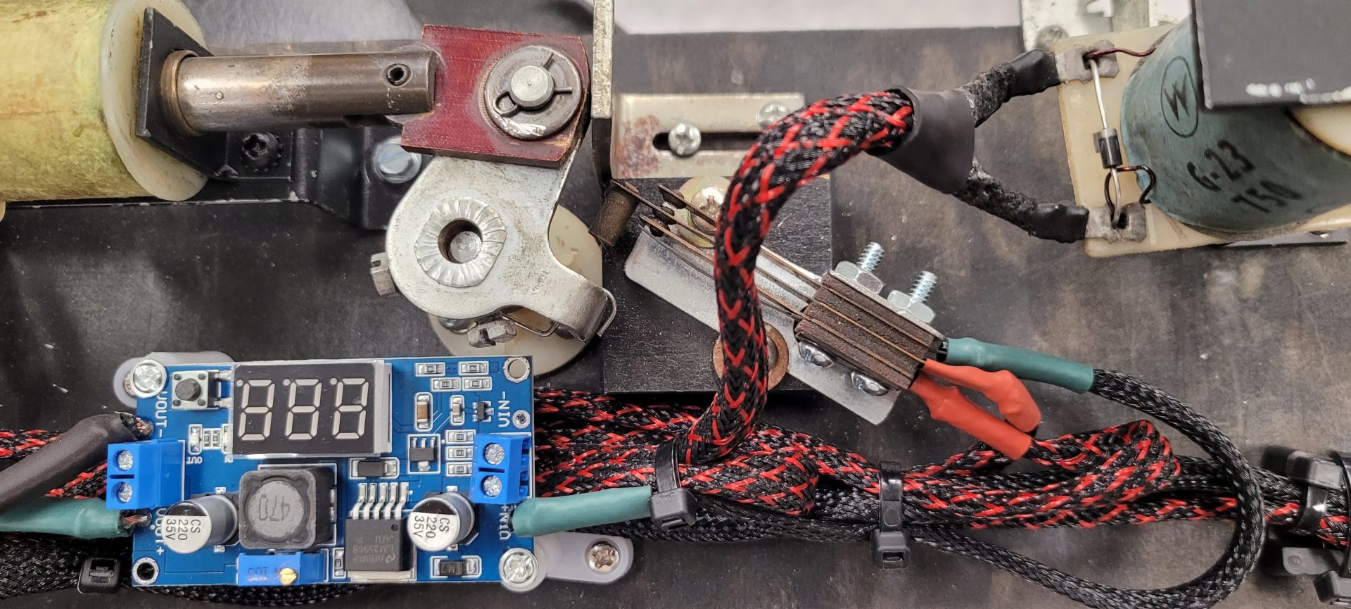
I grabbed a few of the best leaf switches from Tom Tom (the original flipper leaf switches were toast) and built a set of EOS switches for both flippers:
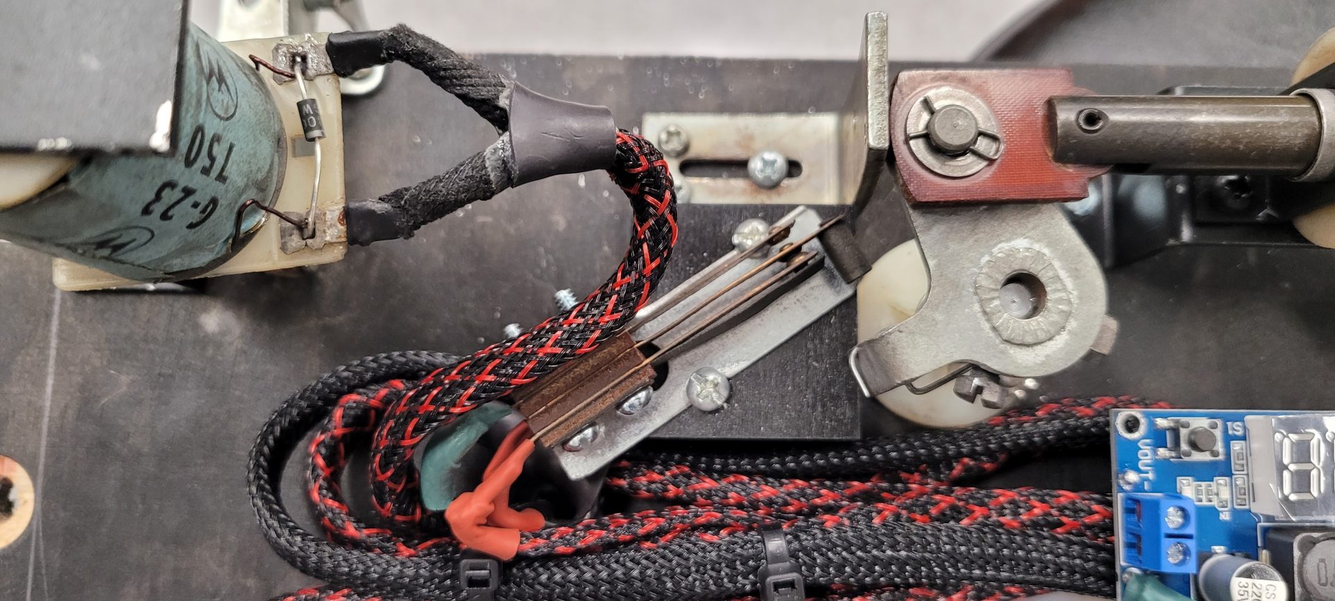
These were wired to a set of DC-DC Buck Converters to do the voltage reduction. These dropped the 24 VDC to 1.5 VDC just by turning a screw:
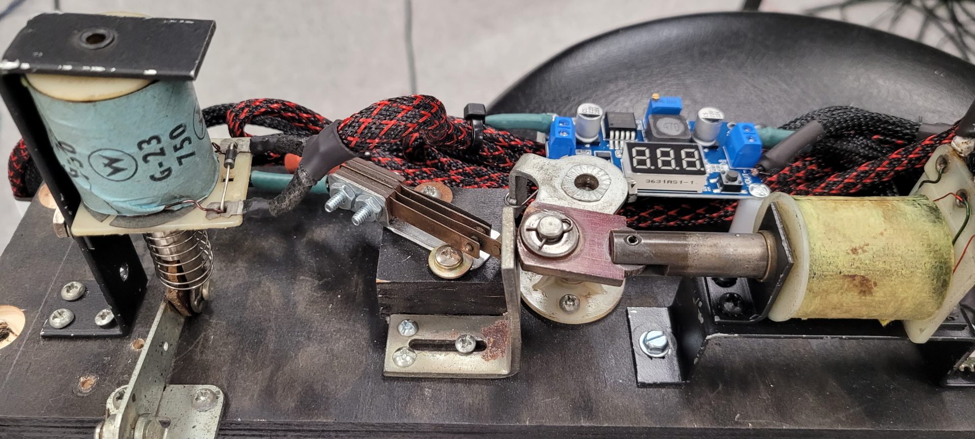
The two remaining slingshots were added to the outsides and by the time it was finished, it was quite the production:
 |
|
 |
|
 |
 |
This module was to be bolted with 1/4″-20 bolts into threaded inserts in the top of the side panels closest to the player.
Each module had wiring that terminated in the appropriate quick disconnect plug that provided power and trigger for each device on the panel, so the rear and center both had 6-pin plugs and the front had two 4-pin plugs:
 |
 |
| Rear | Middle |
 |
 |
| Front Left | Front Right |
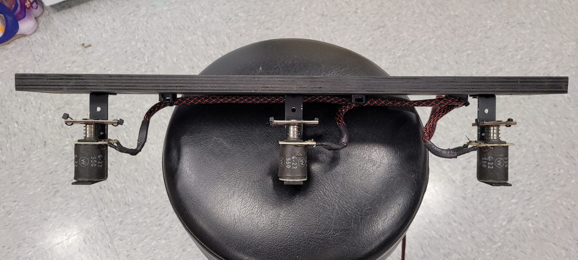
The two bells from Tom Tom were mounted on the wall at the right rear of the cabinet:
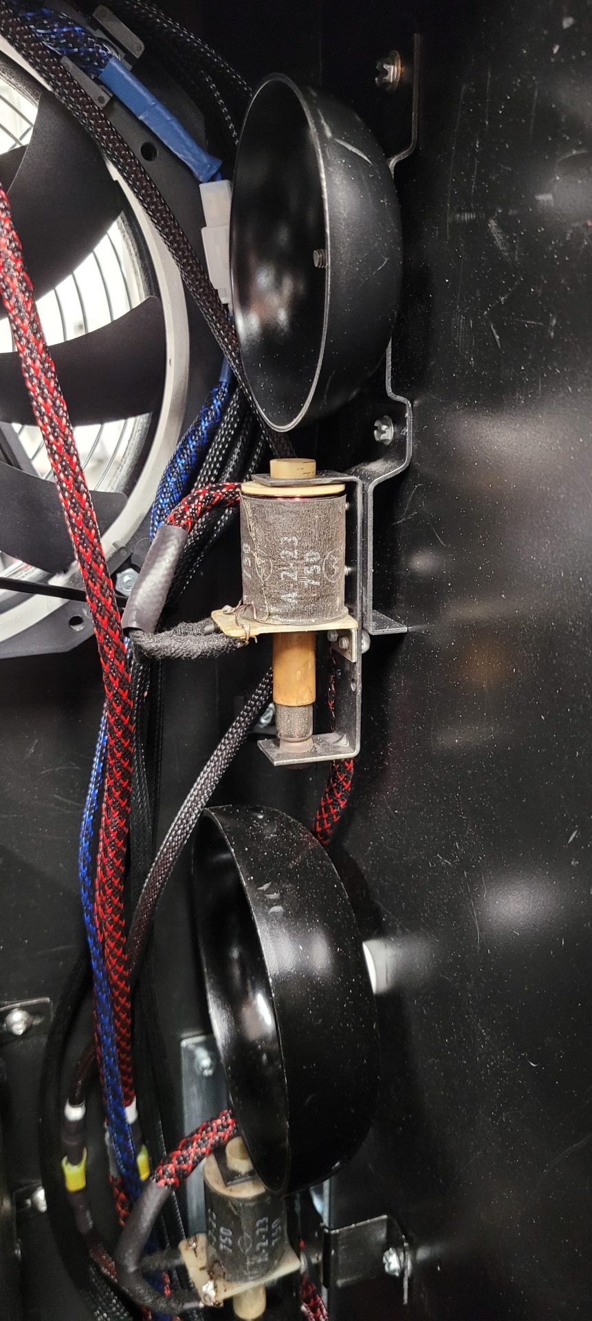
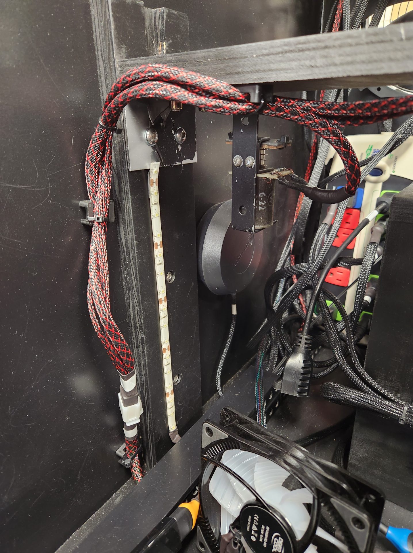
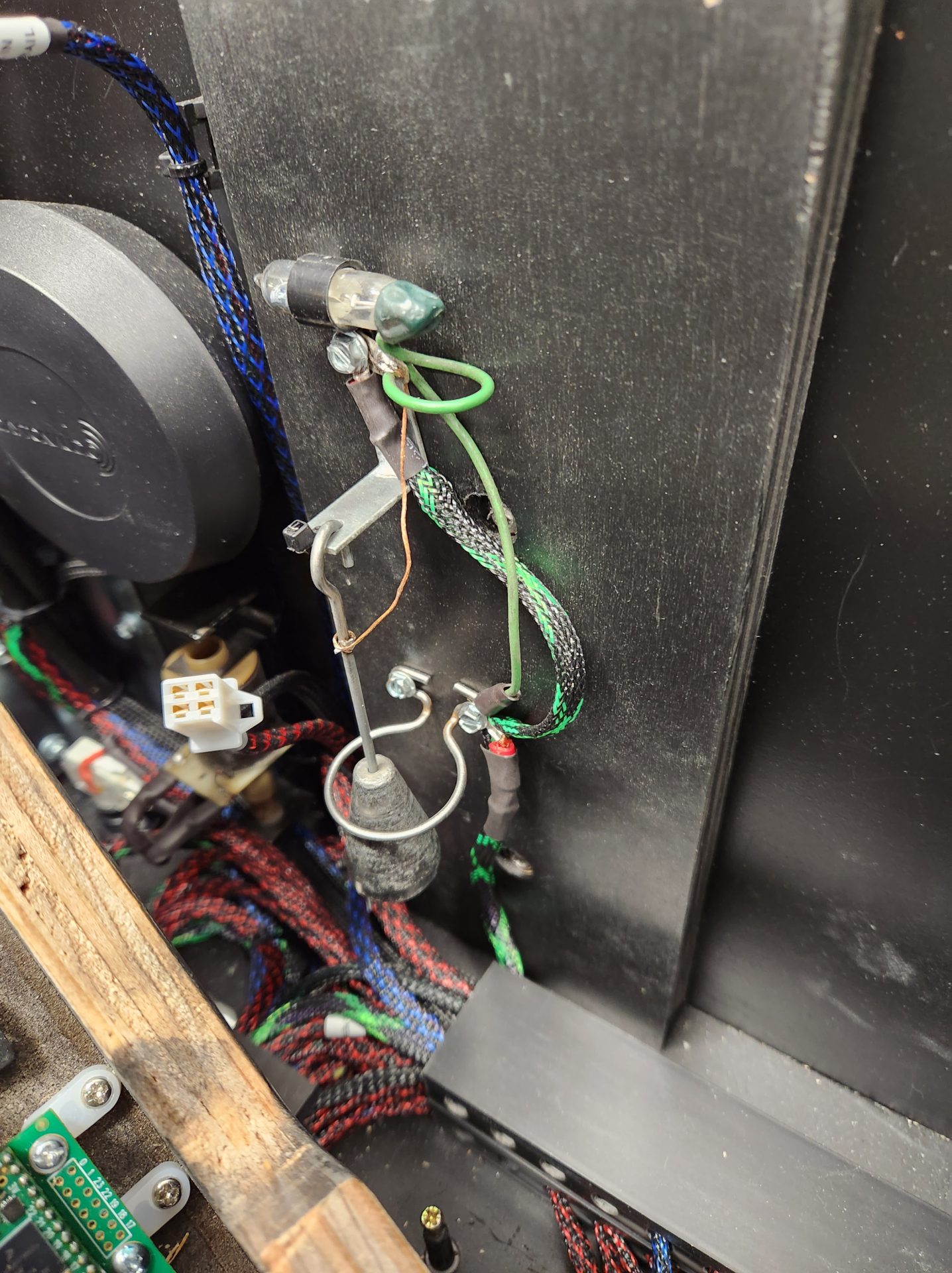
The knocker and tilt bob/mercury switch from Tom Tom were mounted at the front left of the cabinet:
Another major part of this build would be the addressable LEDs. I won’t get into the software portion of adding addressable LEDs, as that is far too complex for me to address (even if I understood it all), but with a lot of reading and experimentation, over the course of about a week, with LOTS of frustration, I finally was able to program the Teensy 4.0, make my cabinet file, program DOF and make my LEDs work as a mockup on the table! Once those lit up the way they were supposed to, I just about cried! This portion was easily the most challenging part of the build for me, because it was purely programming and data – no mechanics and little electronics.
My addressable system would be arranged like this:
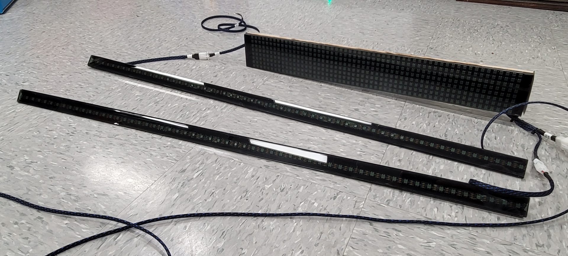
- Left Rail (57 LEDs)
- Left Speaker Grille (45)
- Right Speaker Grille (45)
- Strip on Back box (137)
- LED Matrix (448)
- Right Rail (57)
- Total LEDs: 792
Since the 43″ LG took up almost the entire width of the cabinet, there was no way to mount the rails solidly, as the TV needed to tilt up if needed and be removed if needed. Similarly, the LED matrix needed to be removeable to allow the TV to be removed for service.
What ended up being a blessing in disguise was that the TV had trim on the bottom and top of the screen (which was now left and right respectively), but these trim pieces and the reveal on the monitor were not the same top and bottom so it looked offset in the cabinet even when it was centered. What I came up with was to offset the TV towards the bottom (left side) and mount the LEDs in an aluminum “L” channel, then mount these over the top of the trim of the TV so that when it was all together, the TV looked completely centered and the image on the TV started at the edge of the LED strips.
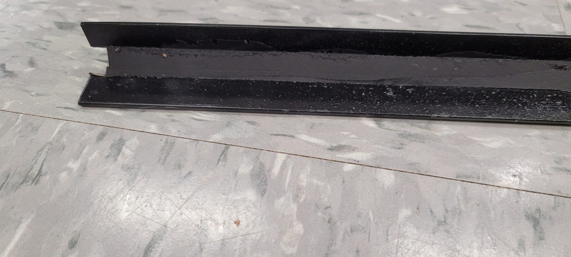
To make the LED rails, I cut some 1″ aluminum “L” channel to length and painted it black. On the end, I notched it out to accommodate the wiring into the LED strip since the channel was EXACTLY the length between the monitor panel at the front and the LED matrix at the rear – no gap whatsoever. I cut a piece of wood at 45 degrees and made the face of the wood piece the width of the LED strip, then glued it into the bottom of the “L”:
I fastened the LED strip to the wood using the adhesive on the strip itself, then cut some 1/4″ smoked plexiglass to cover the strip and used double-back tape to hold it to the channel. Unfortunately, I didn’t have a long enough piece of plex to cover the entire rail so it had to be done in two pieces, but the gap is almost invisible once it’s installed. I may get around to sourcing a chunk of plex long enough to do these in one piece eventually, but that shit’s EXPENSIVE now!:
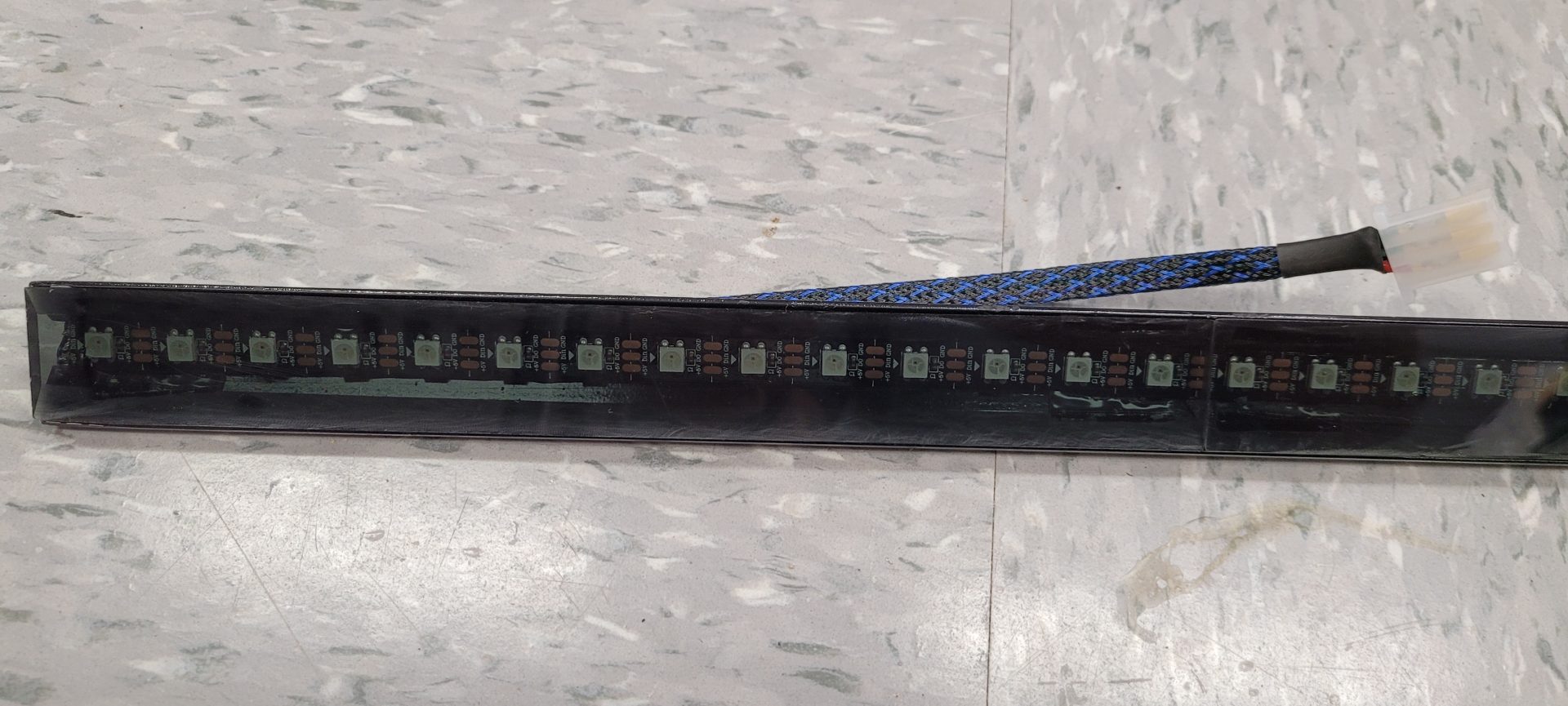
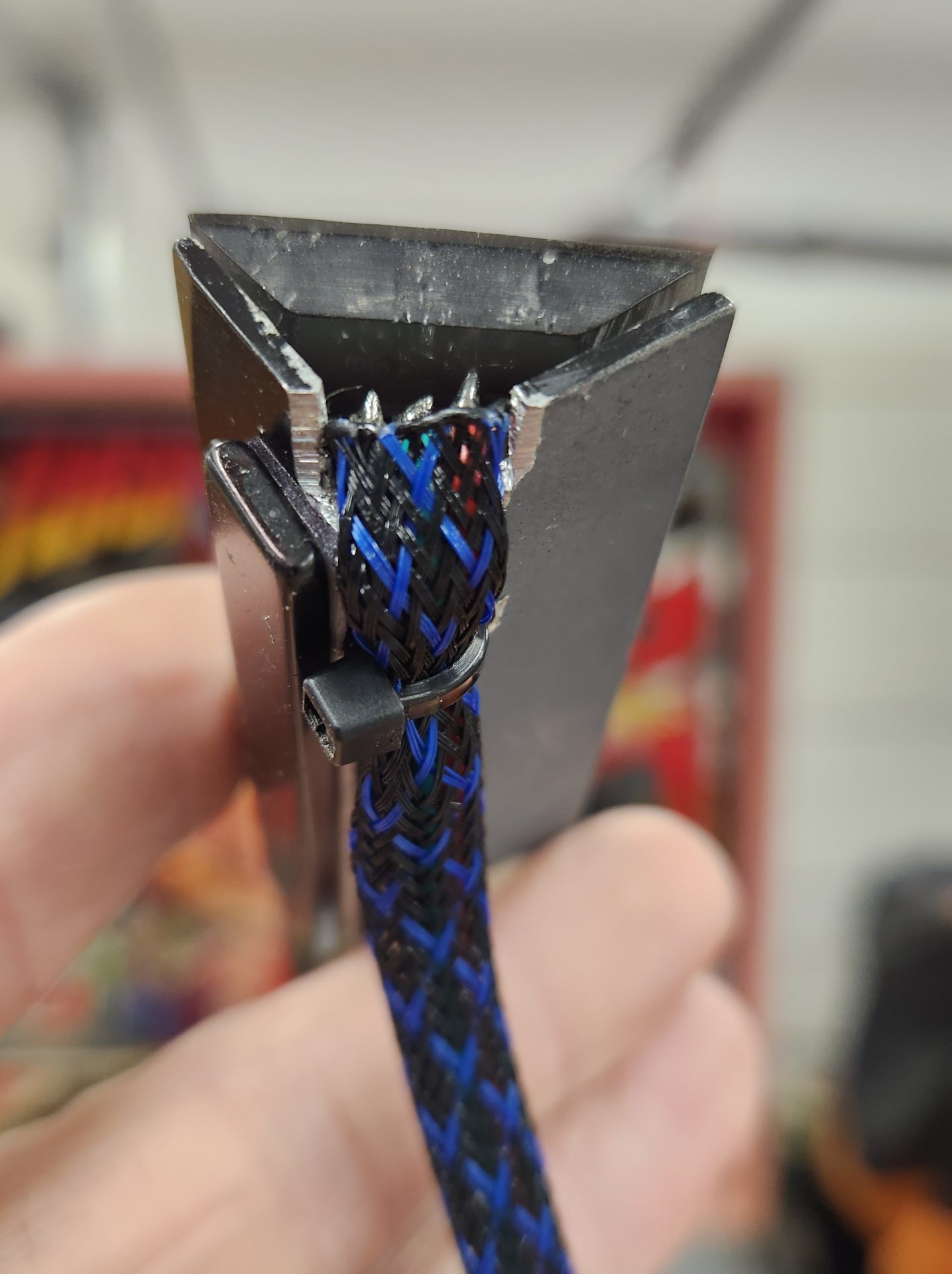
At the end of the rail where the LED 5 VDC and data entered or exited, the notch accommodated the wiring, and I drilled a hole through the bottom of the “L” to add a zip-tie for strain relief:
I used double-back adhesive to attach a flat bar magnet to both the “L” channel and the side of the cabinet that lined up with the magnet on the rail. So to take out the LED rails, you just lift up and unplug them. To reinstall, plug them in and lay them down close to the magnets on the sides of the cabinets and they snap into place (and they WILL NOT move – the magnets are very strong).
Since each rail had unique connectors on each end, there is no way to connect them incorrectly, and each connector has a label anyway:
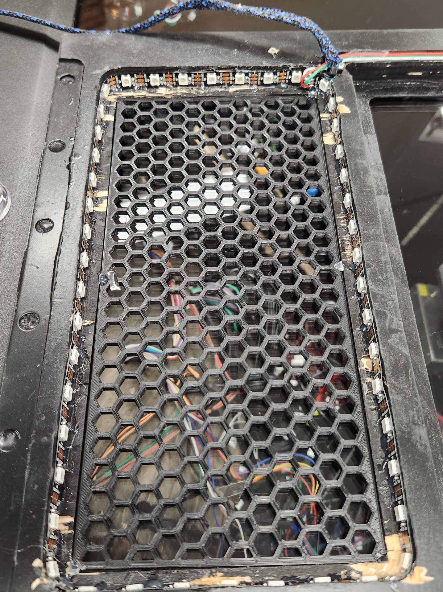
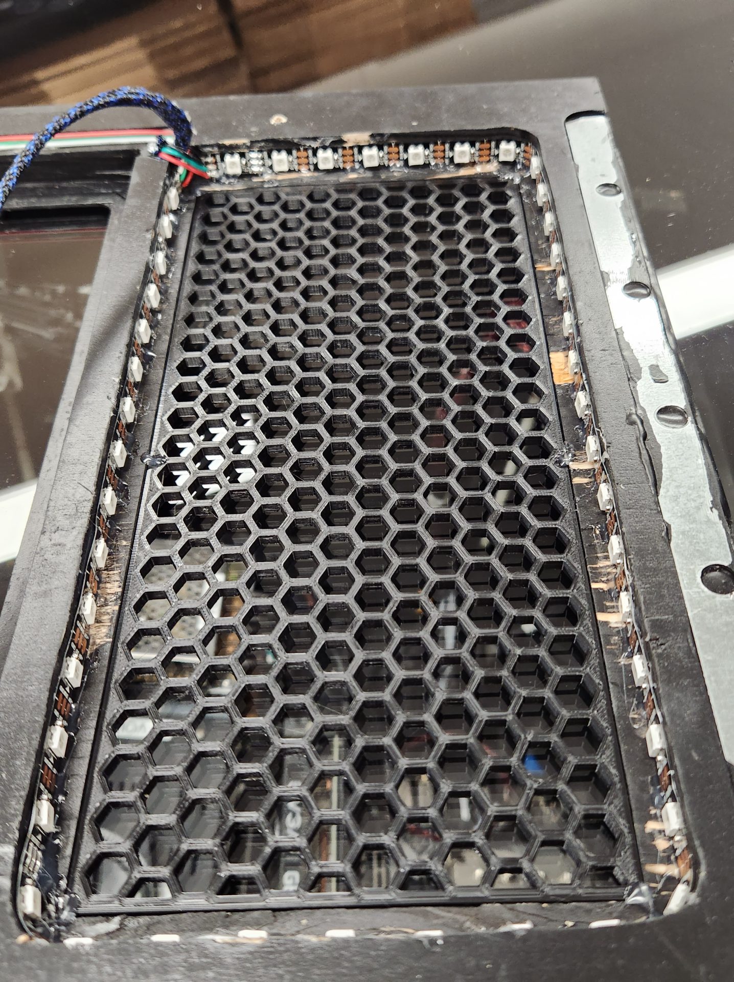
The LEDs continued into the DMD grille panel, with data entering the left grille with 45 LEDs around the circumference, passing over the top of the DMD monitor in a routed channel to the right grille with 45 LEDs, then exiting to the back box strip. These LED strips were hot glued around the inside of each speaker grille:
 |
 |
 |
|
In this design, I wanted to have the two apron monitors at the front and the LED matrix at the rear of the playfield, but this was going to be a challenge, as once the playfield monitor was in, there didn’t seem to be room for the LED matrix to be able to mount as the end of the playfield monitor ended a few inches under the edge of the back box, about where the access holes for the back box cables were. The second issue was that even with no trim around the LED matrix, the height of the matrix itself was about 1/4″ taller than the gap between the playfield monitor and the cabinet’s back box panel.
What I came up with to mount the matrix was to mount a couple of “L” brackets under the lip of the cabinet’s back box panel, spaced back far enough to locate the LED matrix right at the end of the playfield monitor. The matrix panel would mount to this with Velcro, giving me the ability to remove it easily while allowing the panel itself to move slightly once the playfield monitor snugged up against it.
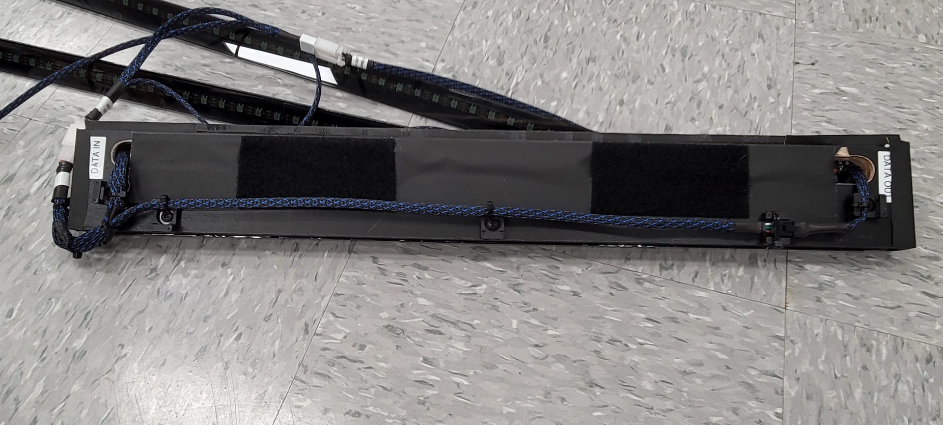
The matrix itself was made from (1) 8×32 and (3) 8×8 panels attached to a piece of plywood exactly the height of the matrix and 1/8″ smaller than the width of the cabinet. I routed a slot down the center of the piece to allow for the wiring to all of the panels:
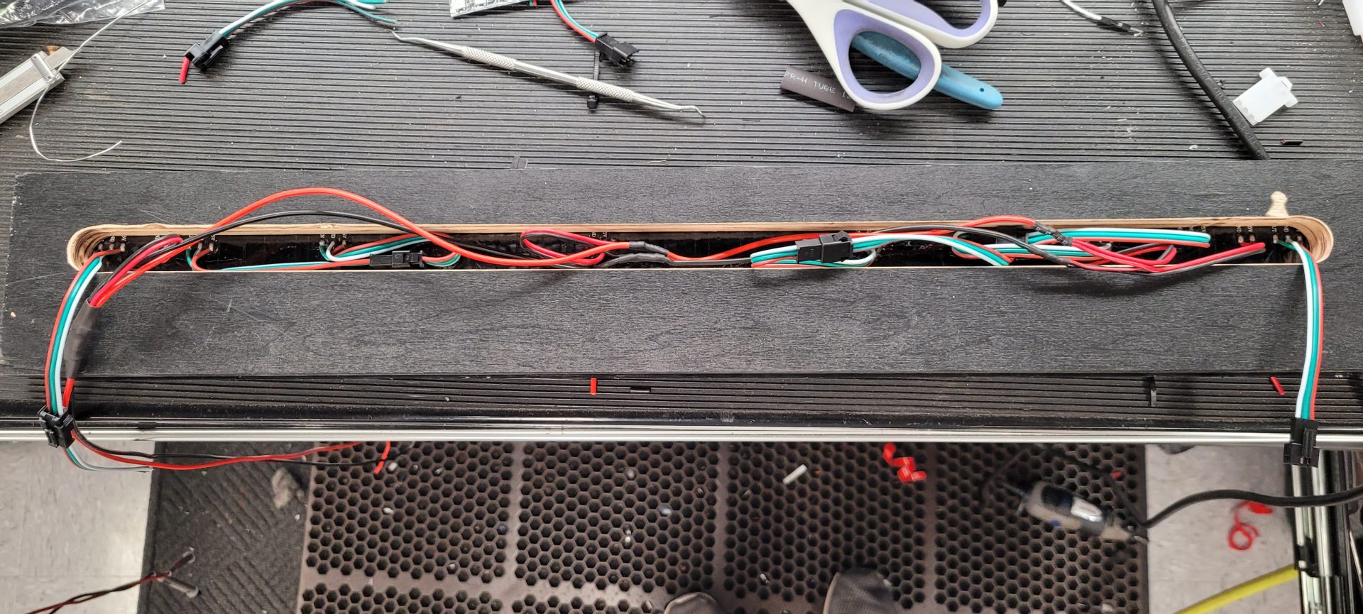
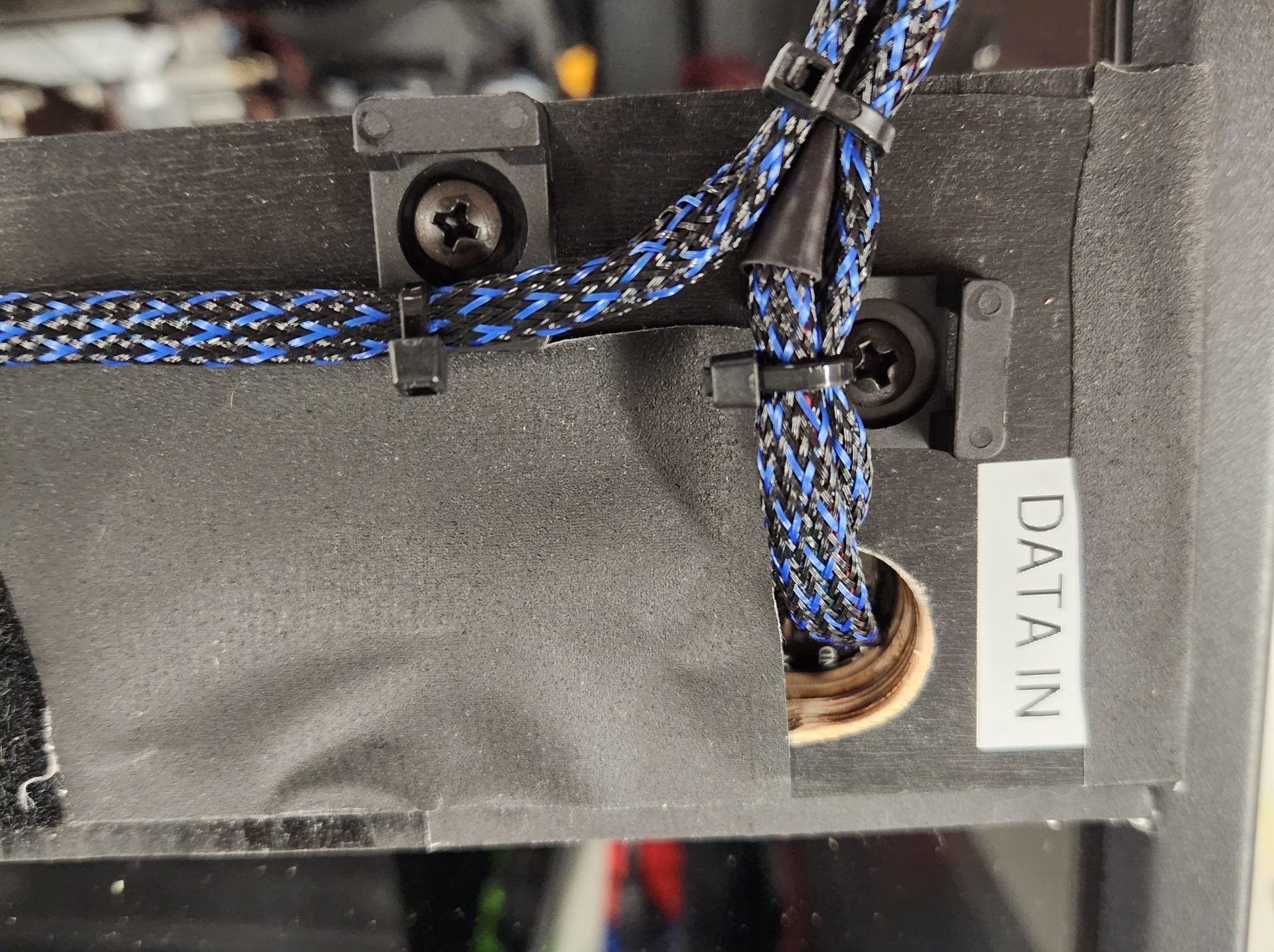
In order for the matrix to wire into the system properly, all of the data and 5 VDC leads were sent to the right side and terminated in quick disconnect plugs – one that got input from the LEDs on the back of the back box and one that output data to the right rail:
 |
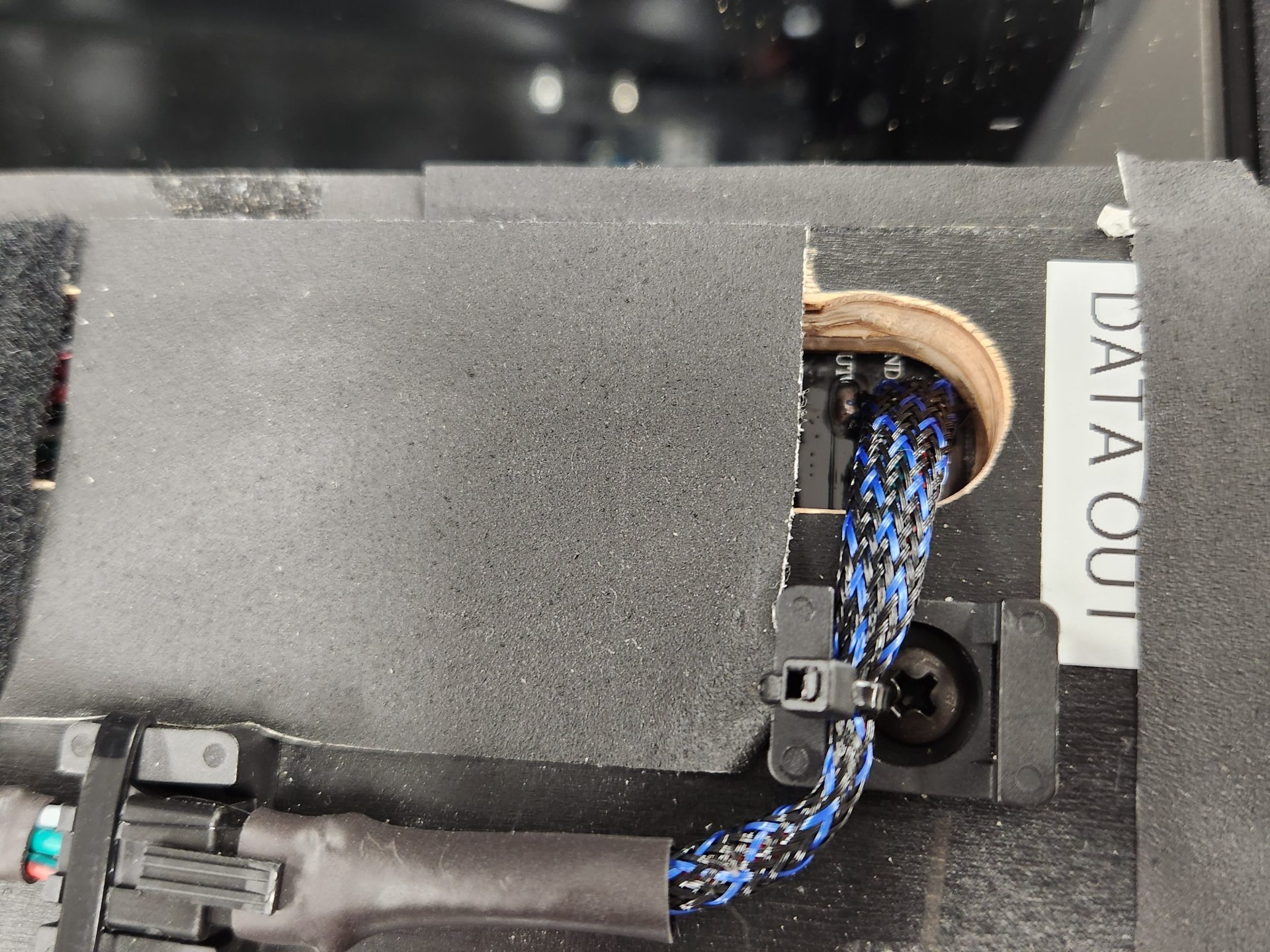 |
On the rear of panel, black gaffer’s tape hides the wiring and the two Velcro patches are what grips the mounting brackets when the panel is installed:
On the front of the matrix, I added a 1/4″ smoked plex panel to help hide the LEDs, which after installation ended up with some additional dark automotive window tint added as well:
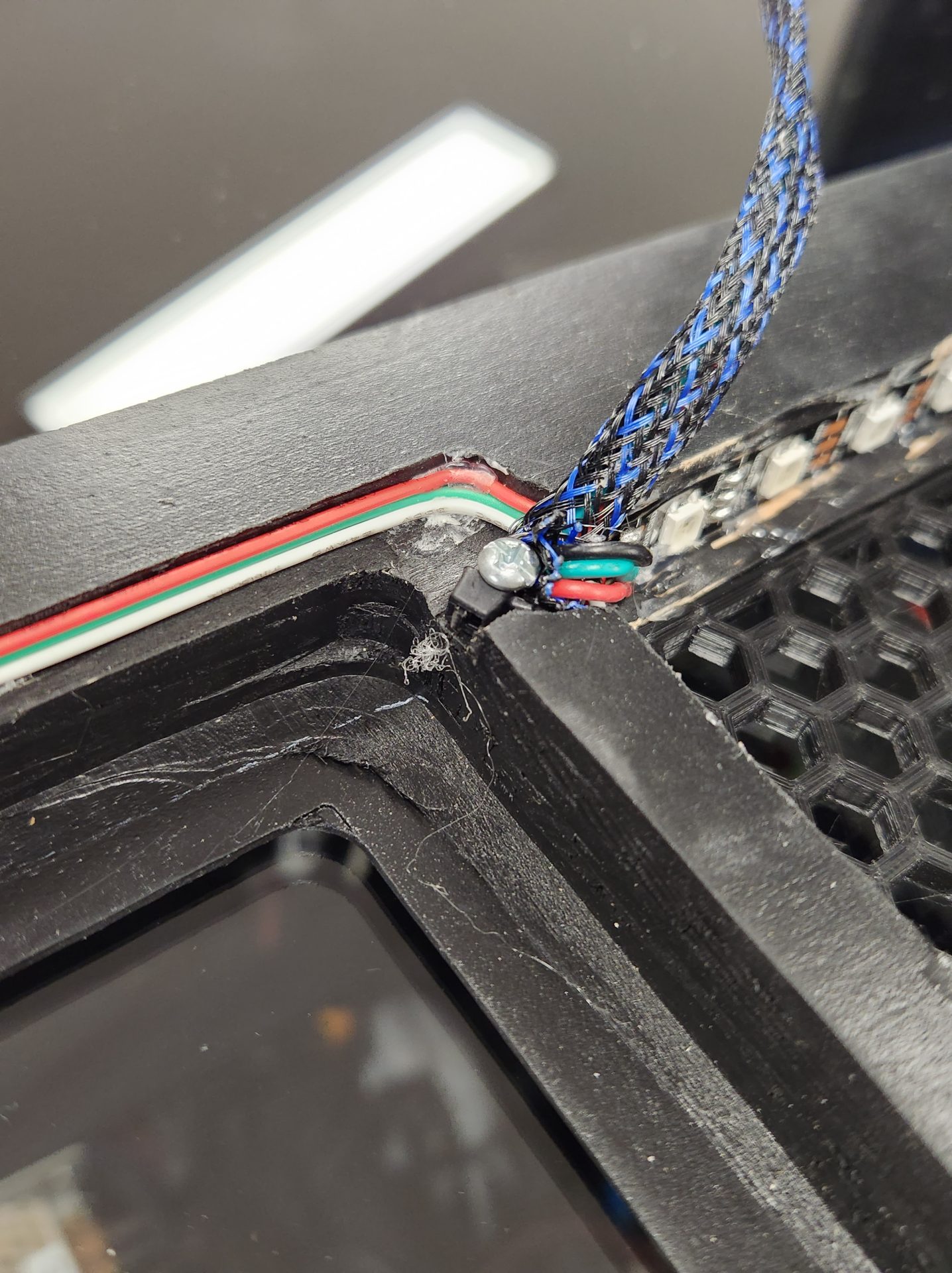
The LED matrix was pretty cool and easy to make, but I ran into one BIG issue not of my making. When I installed all of the panels and wired them up, I didn’t even think to look at how all the wires were connected to the back of each panel – they were new, right? Big mistake, because as I connected everything and tried to get my LEDs working, nothing would fire up on the matrix. All the LEDs would work up to that point, then stop at the matrix. After ripping my hair out for a couple hours thinking it was programming, I pulled the matrix out and noticed one of the harnesses was warm. Uh oh.
Ends up that one of my brand-new matrix panels had the 5 VDC power and ground wires REVERSED from the factory! if you look closely at this picture, you can see the center BLACK wire going to “5V” and the RED wire going to “GRND”:
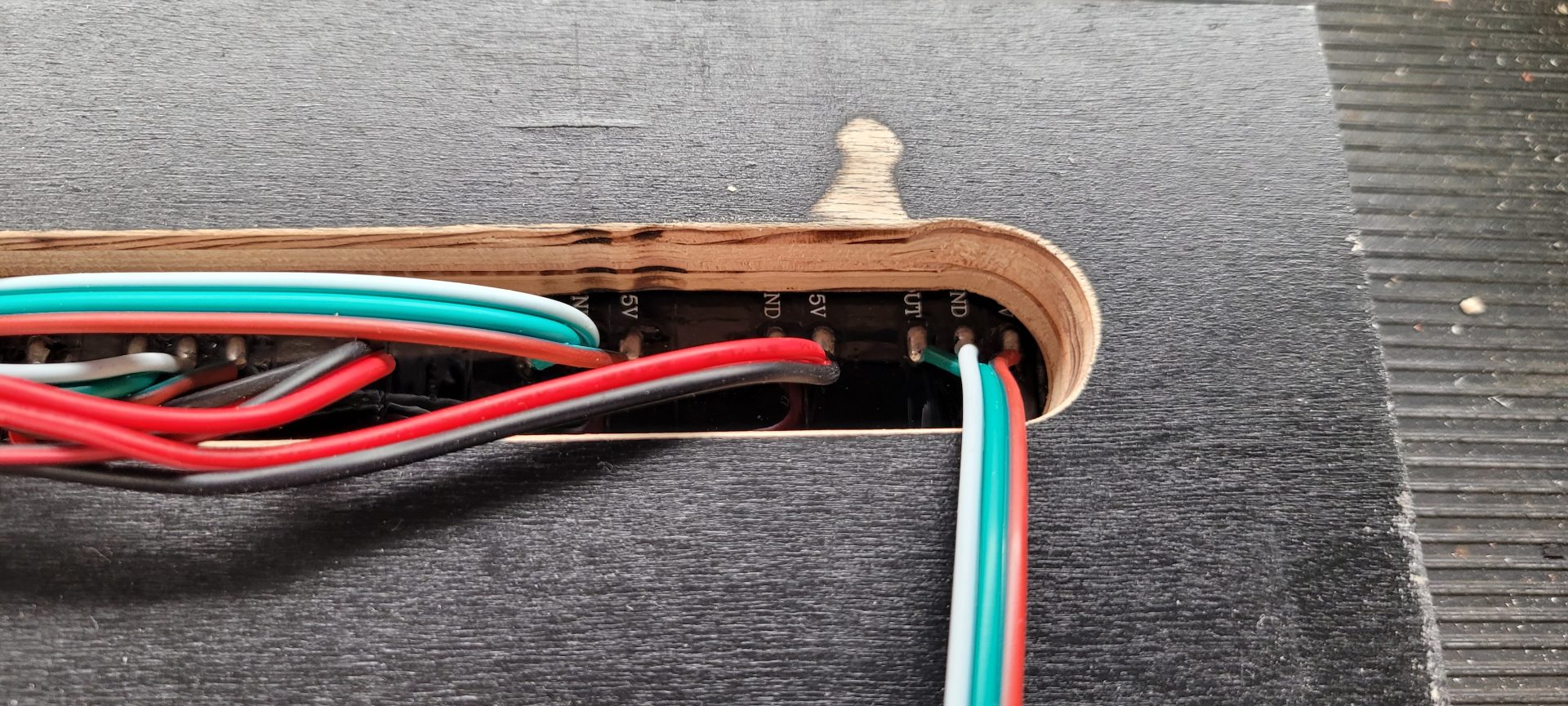
Fortunately, this did no damage to the matrix, the power supply or the wiring, so no harm, no foul other than a couple hours lost to troubleshooting a problem I would not have expected with new parts.
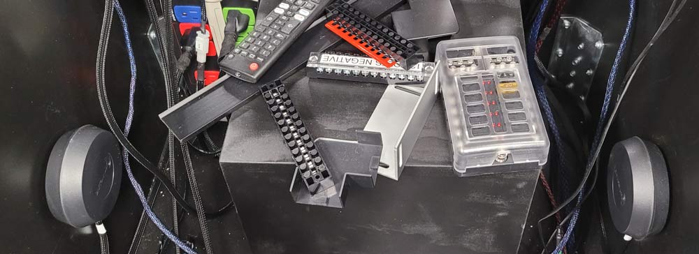
The power supplies for the system were:
- (1) 24 VDC for the flippers/bumpers/slings
- (1) 12 VDC for the amps and 12 VDC accessories
- (1) 5 VDC for LEDs & light bulbs
The power supplies were mounted to the floor of the cabinet in about the middle. The large black and silver box i n the middle right is the 12 VDC supply, while the 24 VDC supply is on the bottom left , with the 5 VDC supply stacked on top of it:
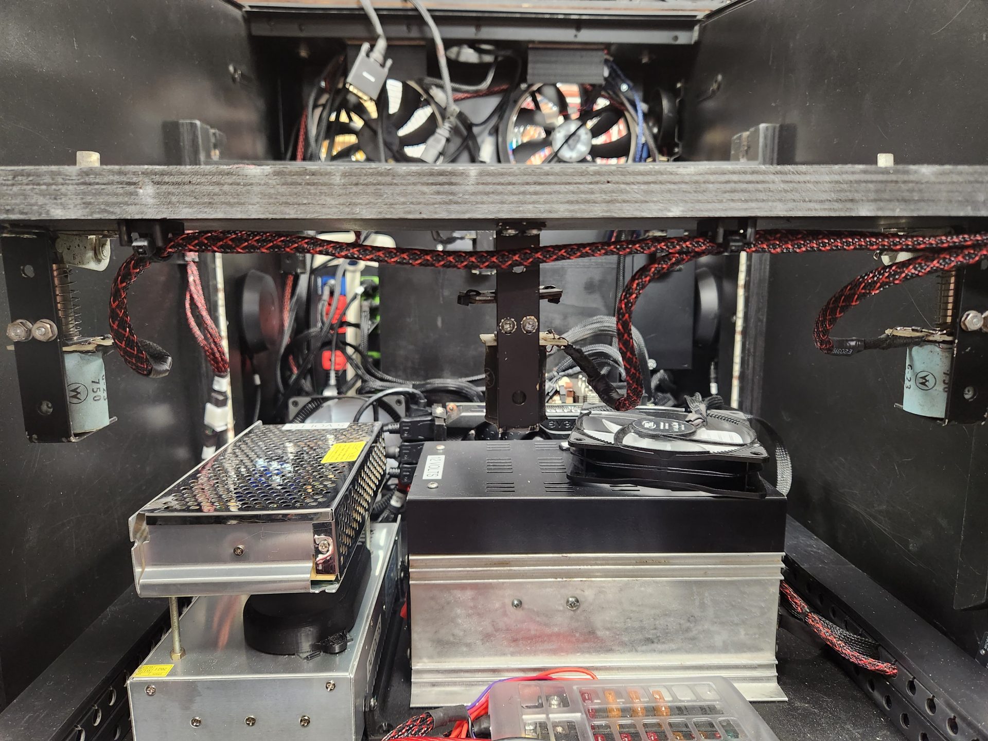
Because the fan on the 24 VDC supply was about the noisiest little fan I have ever heard, I 3D-printed a baffle to cover it and knock down some of the noise (black device on top of the case, and then 3D-printed a bracket to bolt onto the supply in order to screw it to the floor.
In the foreground is a fusebox that I wired all of the 12 VDC accessories to in order to protect the power supply and the system. This is also where each device gets its ground, as the fusebox had a nice terminal block at one end for that use.
The PC was mounted as a free-standing motherboard on standoffs, screwed to the floor:
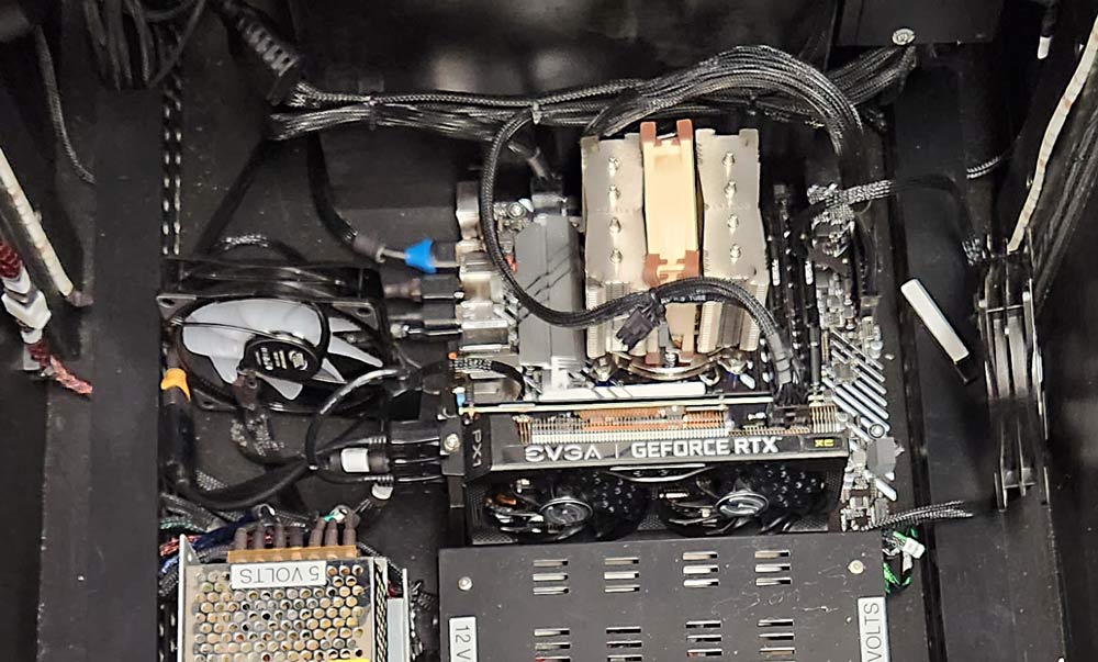
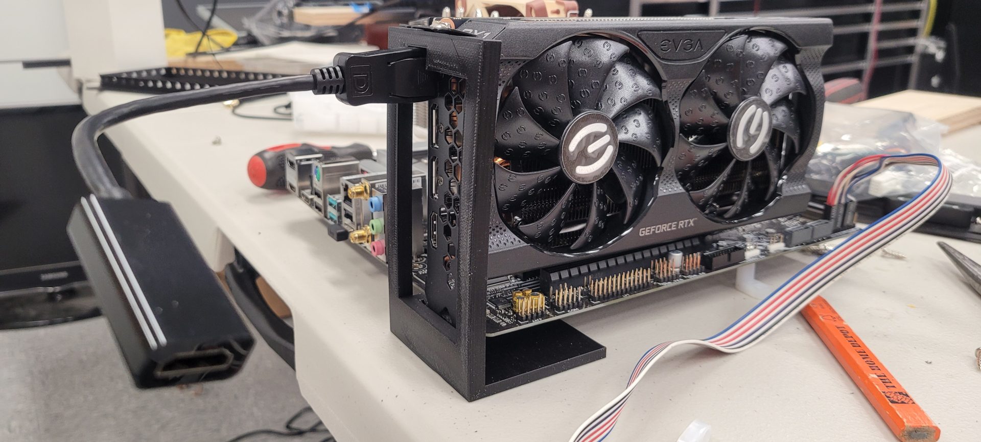
However, mounting it this way posed a problem for the video card – without a case, there was nothing to support the video card. I did some quick measurements and 3D-printed a bracket to hold the video card and also function as a standoff for the motherboard:
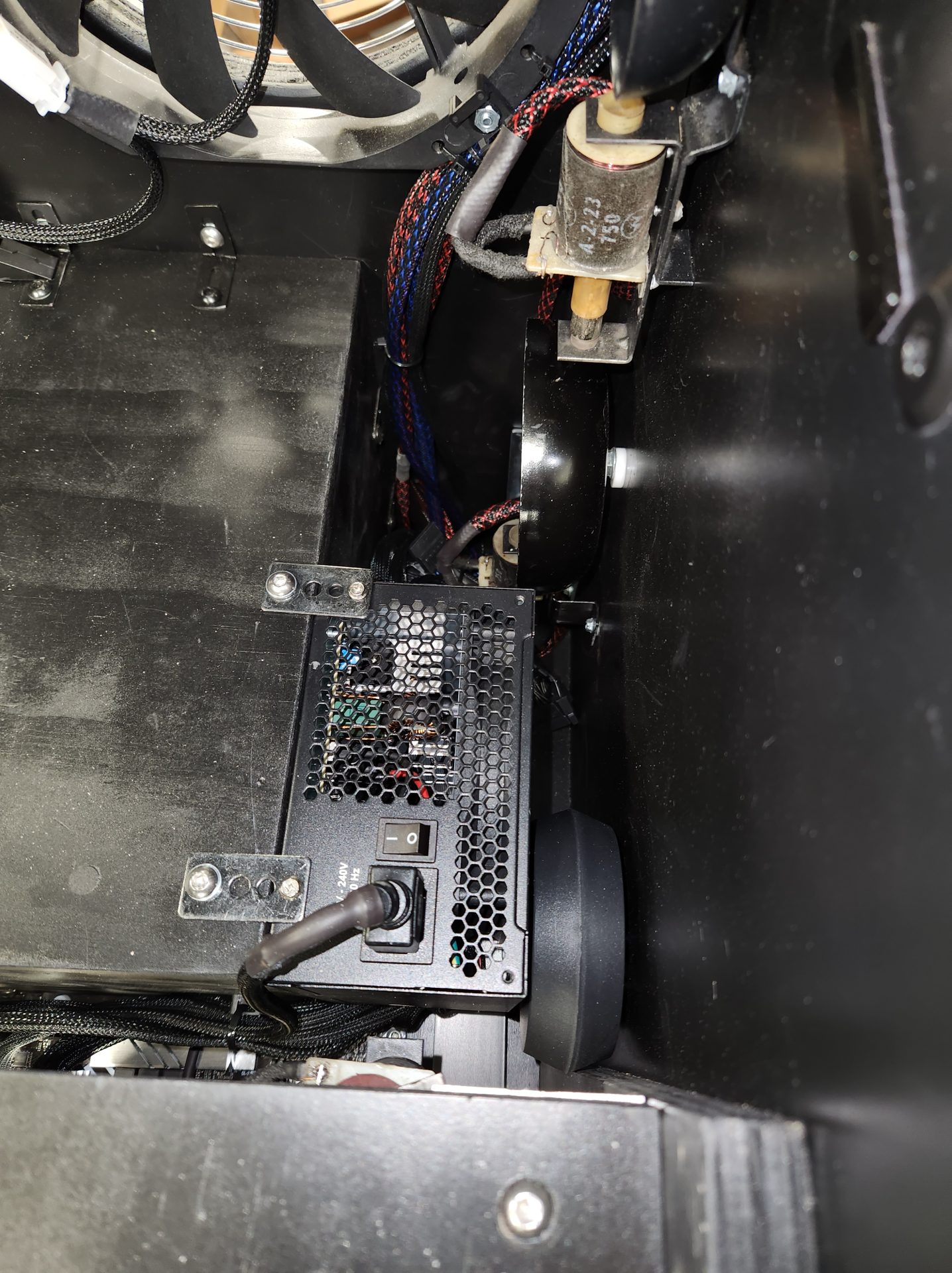
The power supply was mounted to the right side of the subwoofer enclose with brackets and 14″-20 Allen bolts, with a Velcro pad on the back to eliminate rattling from the sub:
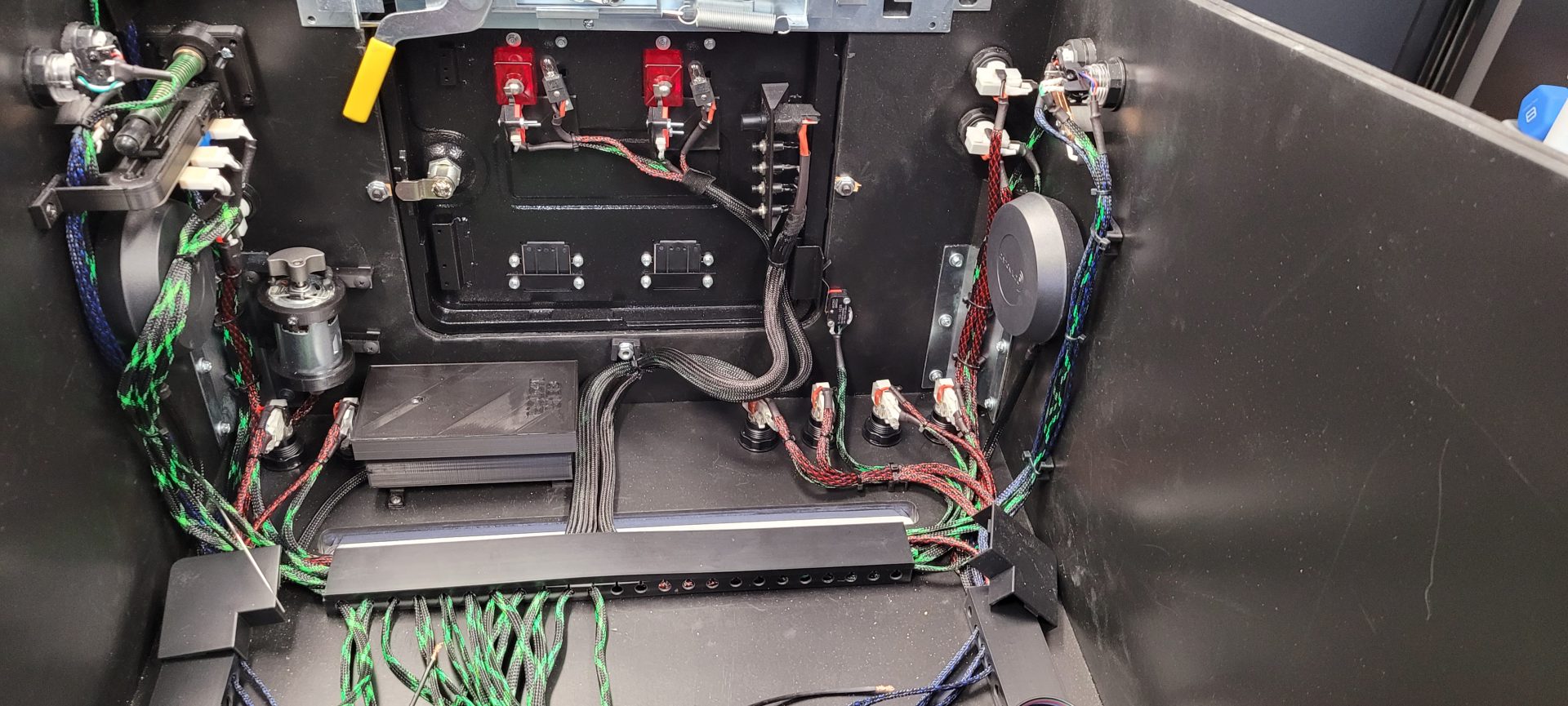
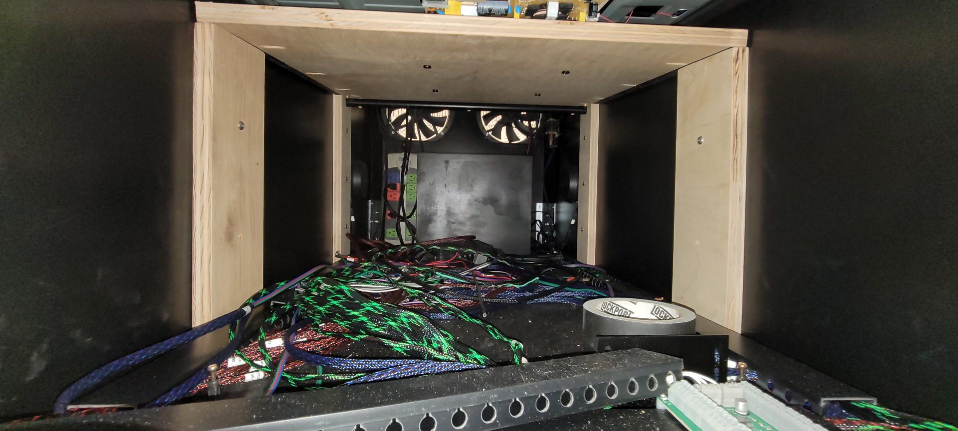
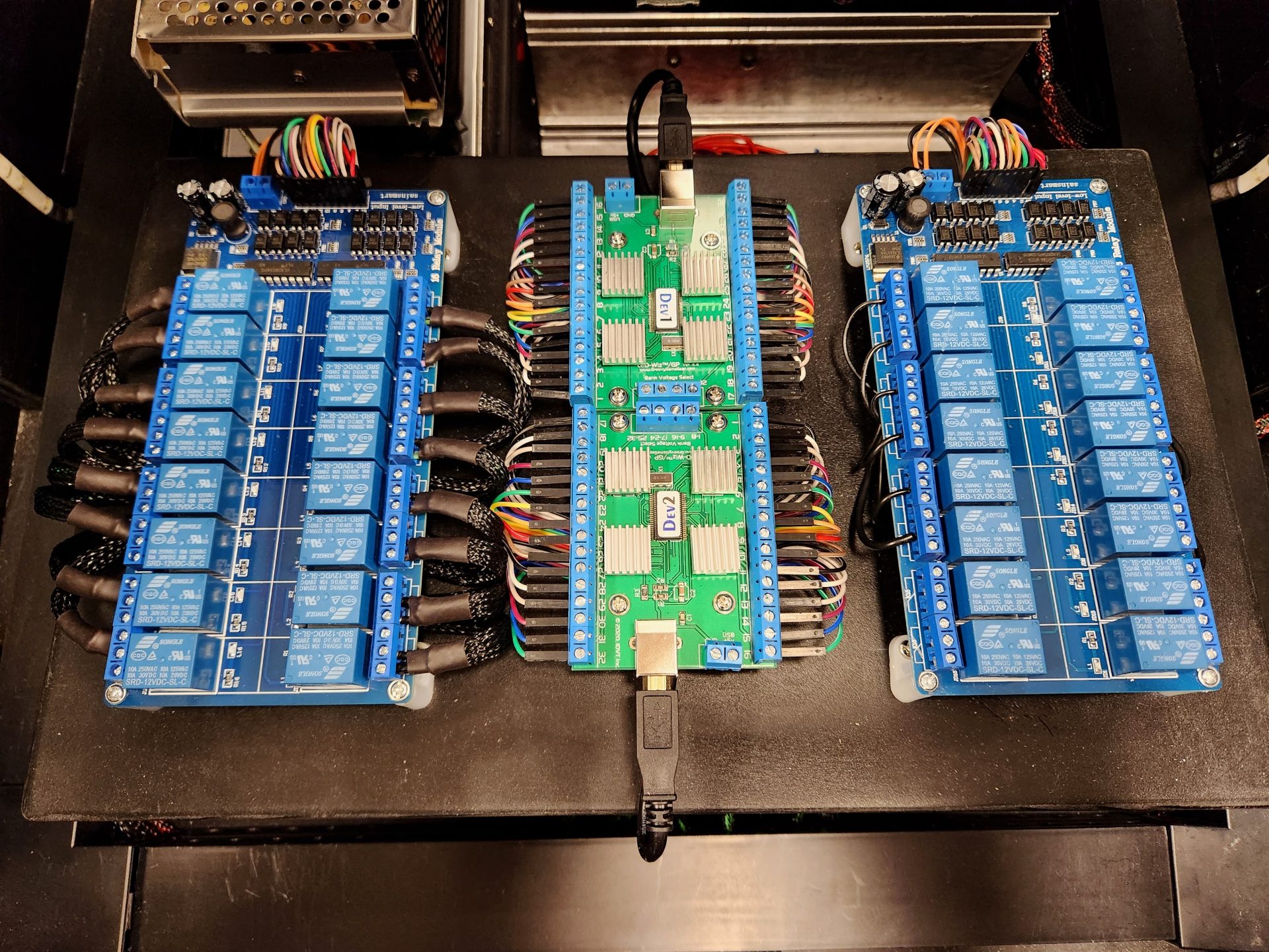
Once the PC was in and functional, I could begin the last bits of wiring, fire it up and PLAY! This lead to one of the most tedious parts of the build – final wiring. All of te control wiring (buttons, plunger) needed to go to the Zeb’s Boards expansion module, while each device that was going to be controlled by the LED Wiz needed to be wired either directly to it (LED’s) or to the SainSmart (solenoids/flippers), and all of this needed to happen at the modules in the front of the cab – it got pretty ugly:
So, there being no substitute for actually doing it, I took about 3 days to finalize all the wiring, which meant that each wire needed to be stripped, soldered, and heatshrunk before it was connected – this happened over 80 times. As an installer, I am used to large wiring puzzles, and this one wasn’t really hard, just tedious. One thing that saved my ass was the nylon sleeving – this made moving wires around during this final phase as easy as it could possibly be – in that pile of spaghetti, I could just pull on a wire and it would come right out – no yanking or tugging – it was awesome and HIGHLY recommended!
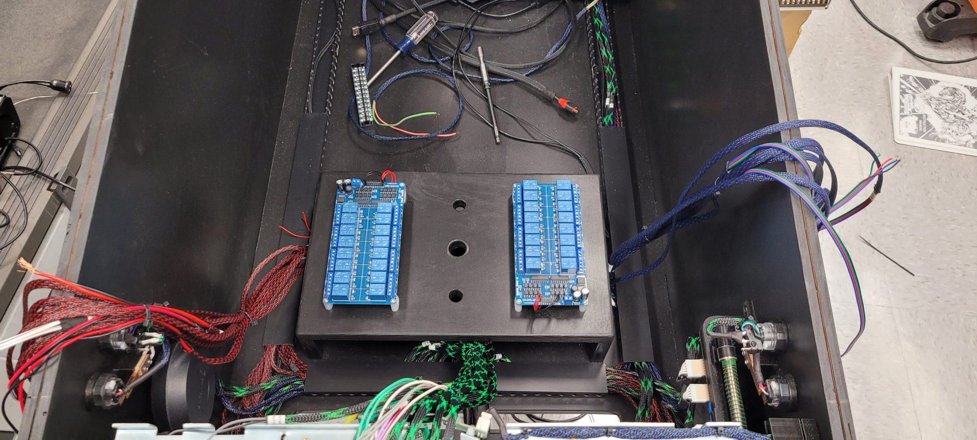
One thing that happened fairly late in the game was adding another LED Wiz due to running out of channels on the first one. Adding the second LED Wiz also allowed me to separate the functions of each module. #1 carries all of the “toy” channels, while #2 does all of the LED channels. This also gives me room to add more stuff as I progress, like a fan and chimes.
So, after it was all done, the modules ended up looking pretty cool and were very organized – the right side SainSmart will be used to the additional “high current” toys when I add them:
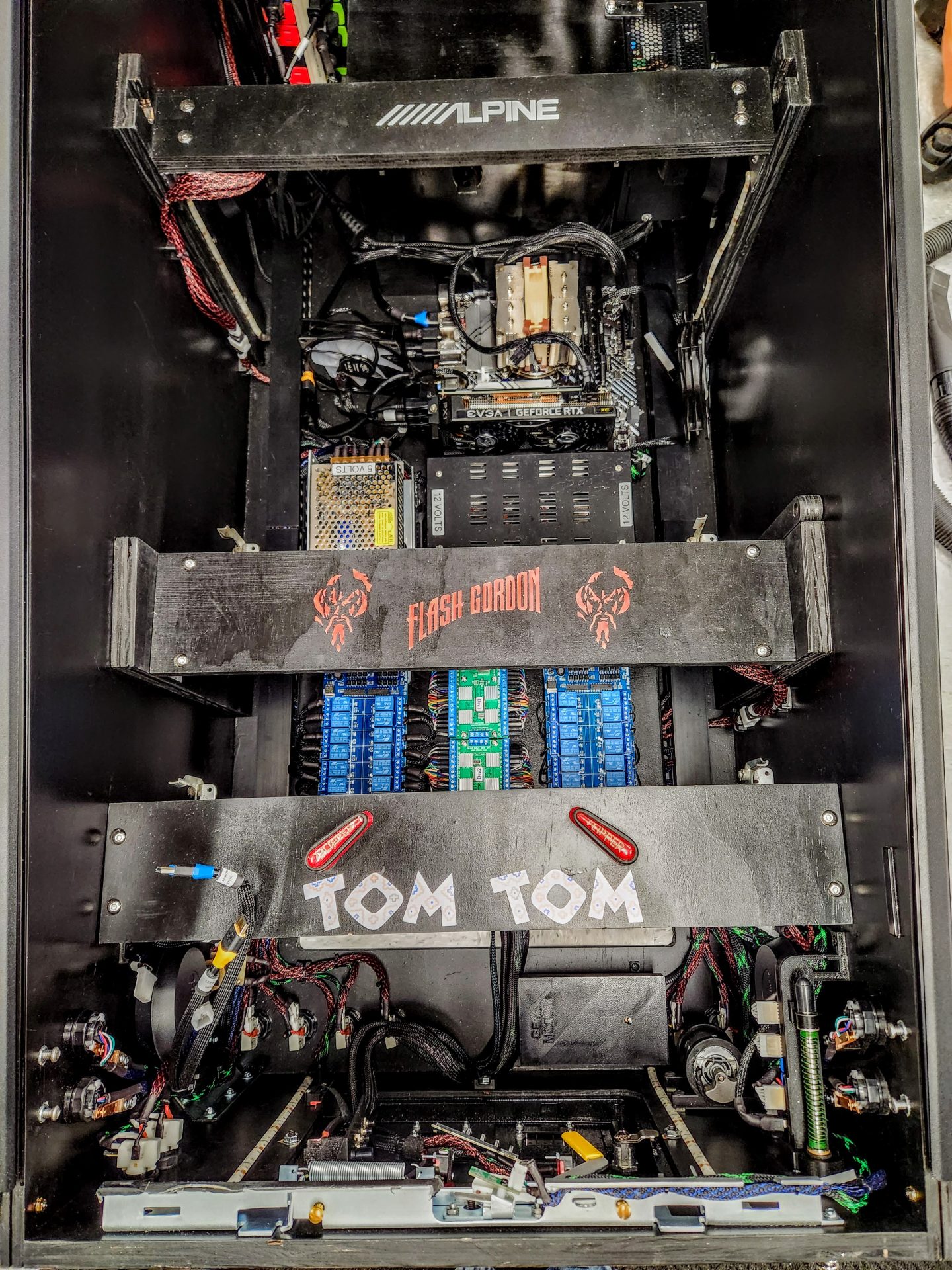
Because I used the old parts from Tom Tom, some from a spare Flash Gordon playfield I own, and the old Alpine amplifiers, I gave them credit on the inside of the machine:
Once the wiring was done and the bottom of the machine was basically all done, I moved to the backglass itself – I had none, so I had to source it. Turned out to be super easy – a 30 1/2″ x 16″ piece of glass was $20 cut to size at my local Lowe’s. I had designed the DMD monitor to accept the bottom of the glass with its trim into a slot on the top of the grille, and with the plastic trim included with the VirtuaPin kit, it fit on the glass and into the slot with no issues. The other trim pieces were added around the edges and the last piece of wood cut was the upper retainer for the glass that was glued to the top of the back box.
The last thing to do was to paint a border on the back of the glass to hide the guts of the 32″ monitor that was de-cased behind it. Some painter’s tape and a black rattle can took care of that, and the backglass was done: