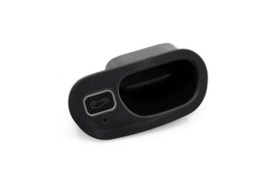
Automatic Power Liftgate Kit for 2013-24 Toyota 4Runner
PLK-TY4RN-2$749.00
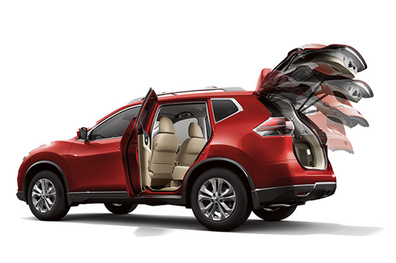
Enjoy the convenience of adding power operation to open and close your rear liftgate with our power liftgate system.
Installation is designed for DIY, but to insure a successful result, we generally recommend professional installation.
Once complete, you will have the ability to open and close your liftgate from the factory remote fob or the front and rear-mounted buttons. An optional foot sensor is available. Manual operation is not changed.
Each kit is fitted with a pressure safety system as well to protect in the event objects or individuals are in the way while closing.
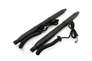
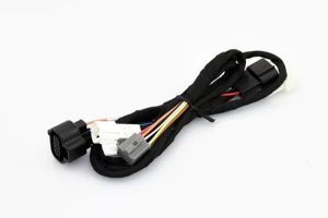
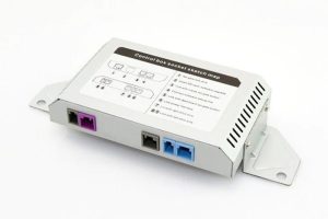
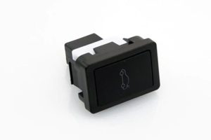
Note: Images are not representative of all kits – each kit will have vehicle-specific rams, mounting hardware, wiring, buttons and installation guides.
NOTE: This is a special-order part and generally require lead times of 10-14 days. Please review our policies regarding special orders.
QUESTIONS? Call 253-297-4570 8:00AM - 6:00 PM PACIFIC
Features:
Customizable gate height.
For safety, gate will re-open automatically if it senses obstacles while closing.
Beeper sounds when tailgate is closing or opening.
Quiet motor, noise less than 50dB at 12″ distance.
Works in all weather conditions, operating temperature is -22 °F~149 °F.
NOTE: This is a special-order part and generally require lead times of 10-14 days. Please review our policies regarding special orders.
APPLICATIONS:
2013-24 Toyota 4Runner: PLK-TY4RN-1
(Writeup below courtesy of trail4runner.com)
TOOLS NEEDED
- The flattest but sturdiest wire fish you can find!
- String or electrical polyline
- Interior panel removal tool
- Automotive grease of your choice
- 8mm hex/Allen key
- 10mm socket and wrench
- Electrical tape
- Plenty of wire zip ties
- Flathead screwdriver
- Philips head screwdriver
- 12” – 15” of an electrical loom roll
- OE Toyota touch-up paint
PARTS INCLUDED W/KIT
- Electric power struts (x2)
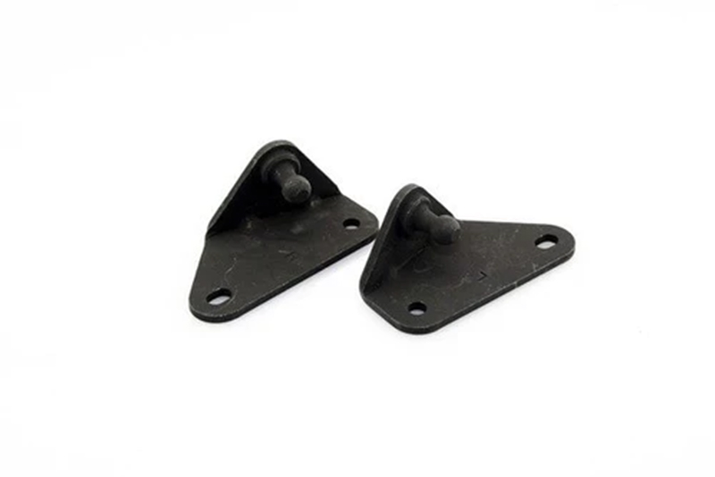
- Upper strut brackets (x2)
- Lower ball studs brackets and washers (x2)
- Control box (x1)
- Power cable with fuse tap (x1)
- Lock assembly (x1)
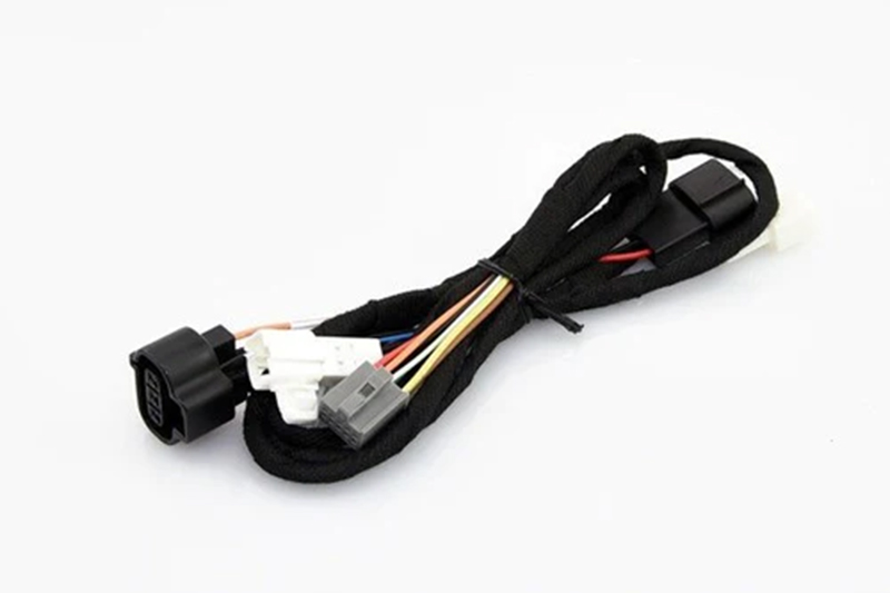
- CANbus cable (x1)
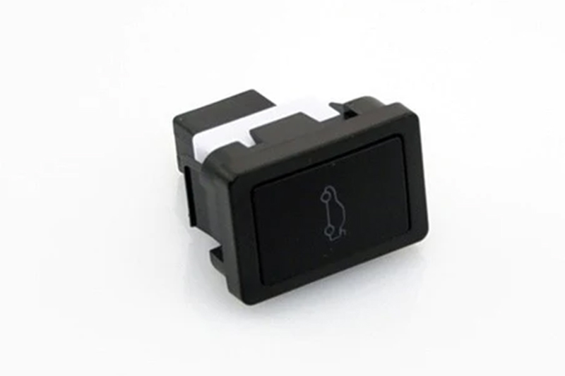
- In-dash button (x1)
- In-dash button cable (x1)
- Rear liftgate button (x1)
- “Buzzer” (x1)
- 8mm hex/Allen screws (x4)
- Zip ties
- Double-sided tape
- Hole saw bit
STEP 1: REMOVE/LOOSEN INTERIOR PANELS

Starting with the tailgate panel, use your plastic panel remover, gently prying from the bottom towards the left and right sides.
There are a series of clips along the bottom, but none on the top as the panel’s rear window interior seal sits on a liftgate ledge. The panel may fall, but the liftgate lights will still be plugged in preventing it from falling completely.
Remove the left light harness and then the right (both have a right-side harness entry).
Place the liftgate panel out of the way as you won’t replace it until the very end of this install.
Now, start loosening the left corner interior panels but note that it’s not necessary to remove them completely as you’ll only be fishing wires through this section.
Note: If you have Rago’s modular storage panels like our rig, it’s necessary to remove the driver’s side completely.
Once that panel was removed, flip up the tab on the left factory cargo tie-down and removed the 10mm bolt.
Using your plastic panel remover, locate the circle tab in the center of the left “hump”. Remove the tab, set aside with the rest of the factory hardware you’ve already removed, and remove the bolt using the screwdriver (P3 head if you have it).
Remove the two upper circle tabs and screws, as well as the jack stand door (it comes in handy later when fishing wires to have this door off altogether).
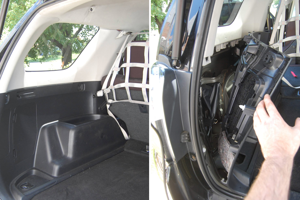
Using the plastic panel remover, slowly go from left to right prying the lower panel away from the upper panel. Again, this doesn’t need to be removed altogether; you just need enough space to fish your wires through and zip tie to points as you see fit.
Next, remove the door sill plastic panels in both the driver side rear and front doors.
The panels pull up easily with a gentle tug but use the plastic panel removing tool if necessary.
We did not remove the panel on the “B Pillar”; you’ll get into loosening the seatbelt bolt and really you just need to fish wires under that section that’s easily done with the good old fashion “shove” method.
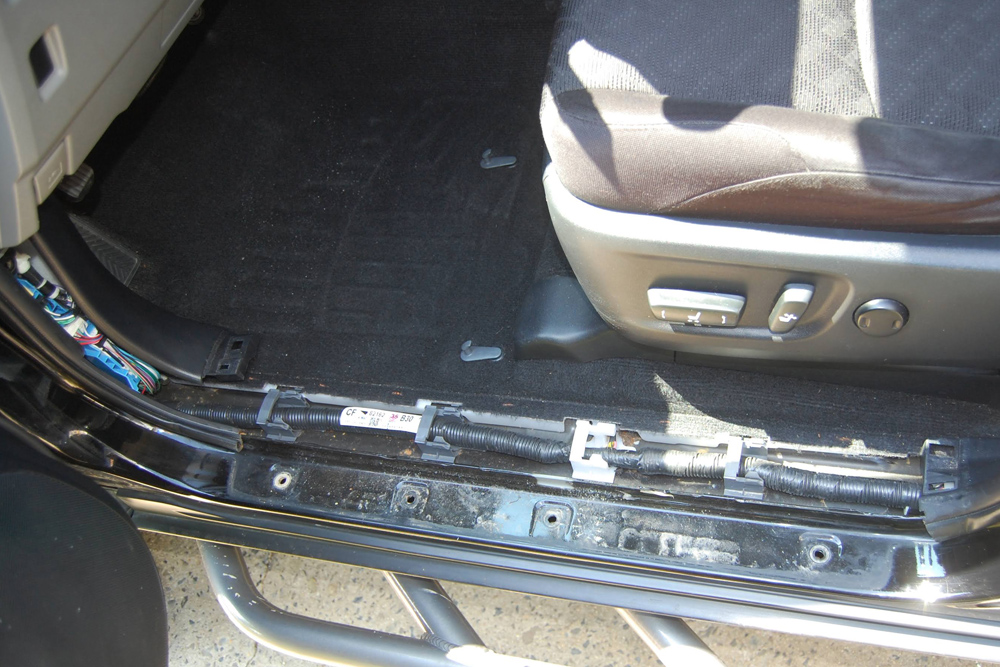
Next, remove the “A-Pillar” left kick panel using the plastic panel removing tool.
Towards the back right side of that kick panel, you’ll notice a “knob”; twist it counter-clockwise and it will remove the kick panel altogether.
STEP 2: PROP LIFTGATE & REPLACE STRUTS W/ NEW POWER STRUTS
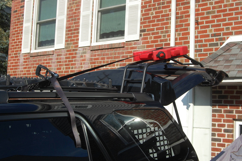
Whenever you’re replacing your liftgate gas struts, it’s good to have a second set of hands.
Since we were replacing the struts but also spending a fair amount of time fishing the wires, we leveraged the rear ladder and roof rack with a heavy duty ratchet strap!
You could use a 2×4 or have a friend hold the gate up for 2 – 4 hours, but the ratchet strap method kept the area free from obstruction and the potential of accidentally kicking out the support… and dying.
Once you feel confident your gate is properly supported, begin removing the existing gas struts. Both tops and bottoms have a retainer clip. Use the flathead screwdriver to back away those clips from the mounting points.
Once the clips are backed away, both struts should disconnect from the ball joints with a little force.

Next, remove the OEM strut ball joints on the bottom and the mounting brackets on the top using the 10mm ratchet.
Before installing the new hardware, we greased all the holes for good measure.
Now, install the mounting brackets provided with the kit. The upper mounting bracket ball joints should be facing inward towards each other. Use your 8mm hex/Allen wrench and tighten the brackets into place using the provided screws.

Next, make your way to the lower ball joints and make sure to tighten them into place using the provided washers.
You’re now ready to mount the electric power struts.
Making sure the wired-side is on top, simply snap the new struts into place.
At this point, you should be able to remove whatever mechanism you used to keep the liftgate propped open (the struts are strong enough to hold the gate into place, even without power).
STEP 3: TAP INTO CAN WIRES, INSERT FUSE TAP & IN-DASH BUTTON

Locating the correct CAN wires was the biggest challenge for us. Once we located the correct wires, it was pretty straight forward from there.
Locate the twisted blue and white wires behind the kick panel.
Note: There are a lot of blue and white wires back here! The CANbus wires, however, should be slightly twisted together and wrapped in a piece of green tape.
Using the pre-assembled wiretaps on the end of the CANbus cable, tap the blue CANbus wire with the white wiretap.
Then, tap the white CANbus wire with the yellow wiretap.
Because the wires were so thin, we wrapped a bit of electrical tape around the taps. Space is extremely tight back there, so taping them up can be challenging.
NOTE: ONLY CONNECT THE WIRES REFERENCED IN THE MANUAL INCLUDED WITHT THE KIT IN CASE ANY INSTRUCTIONS HAVE CHANGED!
Now in the same location, you’ll need to remove the 30A fuse in location #10 from the fuse block.
Using the power cable with the fuse tap, reinsert the 30A fuse you just removed into the open space in the fuse tap (i.e., you now have two fuses in the fuse tap). Insert the fuse tap back into location #10.

Once you’ve decided where you’ll place your in-dash button, connect the button to the back of the front button cable.
We installed ours to the bottom left of the steering wheel using an existing blank.
Lastly, connect the ground wire to the bolt underneath the fuse panel. You’re now done with all front side vehicle wiring.
STEP 4: FISH WIRES FROM FRONT TO BACK

We found that this was actually one of the easier steps.
With all of the panels removed, simply bundle the three sets of wires (the in-dash button cable, the power cable and the CANbus cable) and begin routing them through the plastic tabs on the floor panels. The tabs unclick making the path pretty easy to navigate.
We went back once everything was wired in and zip-tied everything to the existing black loom along the floor.
After you lay the wires down on the driver’s side front floor panel, we just tucked the wire bundle underneath the “B Pillar” plastic we chose not to remove.
Moving your way towards the back of the truck, follow the same process along the rear driver’s side floor panel leaving the wire bundle on top of the rear driver’s side seat.
From there, move into the trunk space and begin pulling the wire bundle into the slightly opened rear panel.
This is where having the jack stand door off comes in handy.
Again, once everything was installed, we went back and zip tied the wire bundle to various points behind this panel to avoid shaking, rubbing, etc.
You’re eventually going to have to run that wire bundle up the left panel towards the liftgate hinge section. That small lighter colored panel just pops off. Don’t worry though, it easily pops back in.
You’ll notice three buttons along the back of the headliner.
Using your plastic panel removing tool, or a clean flathead screwdriver, pop those out as well. We started shoving the wires behind it, but it eventually bent the headliner.
Note: Don’t make the mistake we made; remove the three buttons and pop them back into place at the end of the install.
STEP 5: DRILL HOLE FOR REAR LIFTGATE BUTTON & FISH WIRES THROUGH LIFTGATE
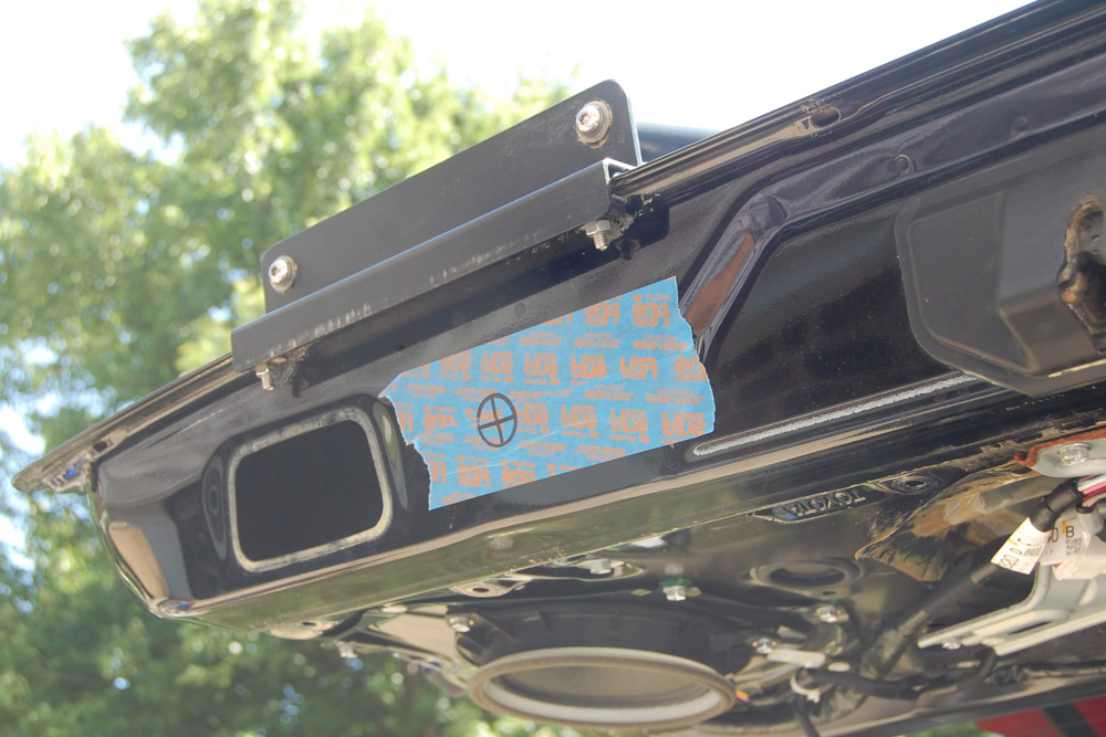
To get started, remove both speakers from the liftgate. You’ll use the speaker spacing to pull the wire fish through. Then, remove the left side liftgate plastic handle.
Prepare the area where you want to install the rear liftgate button. We opted to install the button to the right of the liftgate handle you just removed to give it an OEM look. Others have installed the button inside the actual liftgate plastic handle.
Tape the area off and trace the button’s rear circular shape to the location. We drew center lines and began drilling using the provided hole saw bit.
Once the hole was drilled out, we removed the tape and painted the exposed metal using a little bit of Toyota color-matched black touch-up paint. The whole is completely hidden by the width of the push button, but this was mainly done to avoid rust and any car body paint will do.
Once dried, we installed the push button and twisted the plastic nut on from behind which was easy to get to by removing the plastic liftgate handle.

Now is the really challenging part; fishing all of that wiring!
To the right and left of the newly installed power struts, you’ll notice two rubber blanks. It actually makes you think that Toyota had planned for the power liftgate down the road and just never executed on it to keep costs down.
Nevertheless, remove both rubber blanks. These will not be used as the new power strut cables will run through these holes and come with their own rubber grommets.
Now, locate the rubber grommets towards the bottom left and right side of the window.
Remove them and make a small hole in the center. You’ll pull the power strut wires through this section and retain the OEM grommet.
Time to start fishing and again, this is challenging.
We found that the best way to fish the wires through was to start through the hole near the power strut and make our way back to the speaker opening.
It took a few times and you’ll likely hit obstructions, but be patient and jiggle the wire fish around a bit. Eventually, you’ll see it poke through.
From there, we pulled a string/electrical polyline back through.
Using that string, pull the power strut wire through the OEM grommet and follow the process on the other side.

Once both wires are pulled through, make sure the wire is pulled all the way through leaving no excess by the power strut.
The wire can’t sit in the speaker hole forever, so back up the wire ends to the holes that you’re reusing the grommets from.
Then, pull tight on the wire and push the attached rubber grommet from the power strut through the hole where you removed the rubber blanks.

On the left side of the tailgate near the power strut, you’ll notice another rubber grommet with a rubber loom running through it.
The likelihood of being able to pull your wire bundle through that rubber loom is slim. We made a small cut on both grommets, pulled the wire through and temporarily zip tied the wire bundle to the rubber loom.
A few days later, we used a black electrical loom and wrapped those wires and used electrical tape wrapping around the plastic loom and rubber loom. We also suggest going back and using silicone on those holes.
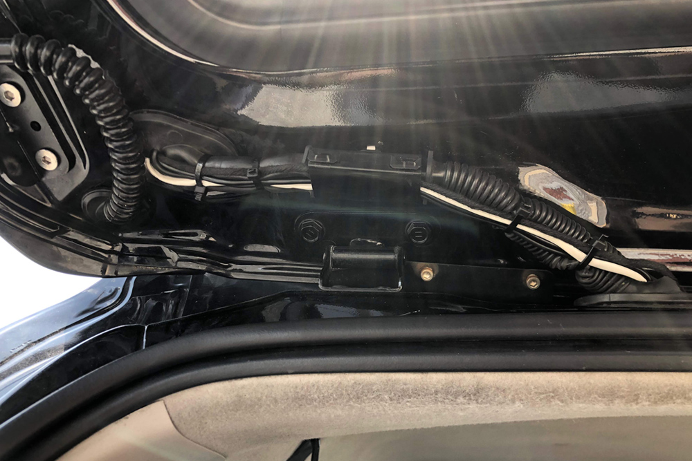
Now you’ll need to pull that wire bundle through the rubber grommet hole and back through the speaker.
At this point, we pulled them through one-by-one and found that fishing through this larger hole was a bit easier.
STEP 6: TAP INTO EXISTING CONTROL BOX & CONNECT ALL WIRES
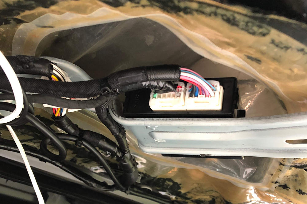
With all of the wires pulled through, you need to tap into one more existing line.
Take the purple wire from the lock release line and locate the gray wire on the left side pin connector connected to the OEM rear hatch control box. You may need to cut back some of the loom/tape.
Once tapped, we applied a healthy dose of electrical tape since the wires are thin.
Connect the rear liftgate button to the lock release line. Make all of the remaining connections to the control, but save the power cable for last.
Connect the buzzer line to the red outlet in the control box.
Once all connections are made to the control box, connect the power. If everything was connected and wired properly, you’ll see the red light on the control box blink approximately 15x’s.
Note: You may hear the buzzer go off as well, but don’t worry if that doesn’t happen.
STEP 7: SHUT GATE & TEST HEIGHT

Before you go back and reassemble all of the interior parts and call it a day, shut the liftgate lid and let the system initialize.
RUN A FEW TESTS FOR OPENING AND CLOSING THE LIFTGATE BY EITHER CLICKING:
- the in-dash button twice;
- the rear liftgate button;
- or the unlock button on the key fob three times.
We suggest trying all three to make sure it works properly.
Also, adjust the height as you see fit. To adjust the height, open the liftgate using one of the methods mentioned above.
Then, manually pull the liftgate down to the ideal height where you and others accessing your cargo area will be able to reach the button.
Once you’ve found the ideal height, close the liftgate. Moving forward, the liftgate should open to that height each time.
STEP 8: ZIP TIE & REASSEMBLE ALL INTERIOR PANELS
Now it’s time to go zip tie crazy!
Make sure all of your wires are in places that won’t cause obstructions and that your tapped wires won’t come loose. Use electrical tape and zip tie where it makes sense.
Once you feel confident everything is secure, using the 3M adhesive strips, fix the AutoEase control box somewhere in the liftgate that won’t come in contact when the window is rolled down.
Also, be sure where you are connecting the box won’t cause issues when reinstalling the liftgate panel.
Follow all of the steps in Step 1 in reverse order and enjoy your new luxurious way of accessing your cargo area!
4RUNNER AUTOMATIC POWER LIFT GATE REVIEW
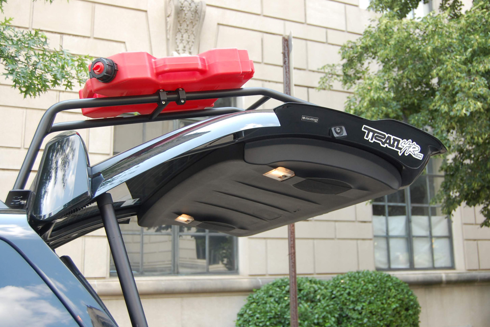
All-in-all, we are very happy with the product.
The installation process described above is 10x’s better than the instructions that came with the AutoEase kit, so you’re welcome and pay it to forward to the 4Runner community when the opportunity comes up!
If you think the steps described above are just entirely too involved, buy the kit and take it to a shop to have it professionally installed.
We called a local Best Buy in the Philadelphia area and they quoted us $375 to have the kit installed, which will likely vary depending on the shop you take it to.
However, installing the kit following the instructions above can take anywhere from 2 – 5 hours and requires patience, especially when you’re fishing the wires through the liftgate.
As for the look and feel, it’s as if the kit was intentionally designed to not look “aftermarket”.
It blends into the existing design of the 4Runner and like we mentioned before, some of the blanks on the tailgate lead you to believe that down the road, Toyota had plans of adding this as either an add-of feature or something specifically for the Limited and TRD Pro models.
PRODUCT WARRANTY: ONE YEAR
Our goal is to answer all of your questions in advance so your purchase and installation goes as smooth as possible. We want to help you choose the right product for your vehicle and your priorities.
Since most electronic products are not eligible for return and refund once installed, and those that are will incur a restocking fee, it is critical that you understand the features and limitations of the products you are considering.
Please call 253-297-4570 if you have any questions about the products you are considering before your purchase or for support after your purchase, and we will be happy to help!
Please also take time to visit our POLICIES PAGE for more information and to review our policies regarding your purchase.


