
GM1210 Installation Guide
OVERVIEW OF THE INSTALLATION PROCESSPLEASE READ THIS SECTION, EVEN IF YOU FEEL YOU KNOW EVERYTHING THERE IS TO KNOW ABOUT THE RADIO AND YOUR VEHICLE, AND YOU’VE NEVER READ A MANUAL IN YOUR LIFE When installing the Rosen/Car Show GM navigation systems, there are some basic steps to take to insure that the installation is done correctly. Having been a professional car stereo installer since the mid-70s, trust me when I say that these tips will help you do the job easier, quicker, safer and will cause less damage and headache in the long run…
|
Rear Chassis Ports: |
 Rear Panel Rear Panel 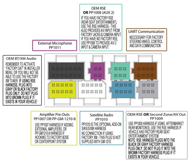 Harness Connections Harness Connections
The rear chassis ports are color-coded and keyed so that the supplied harnesses can only be plugged into one port. Please keep in mind that each installation is unique and that all ports may or may not be populated when you are done. |
Main Harness: |
 GM1210 Harnesses GM1210 Harnesses
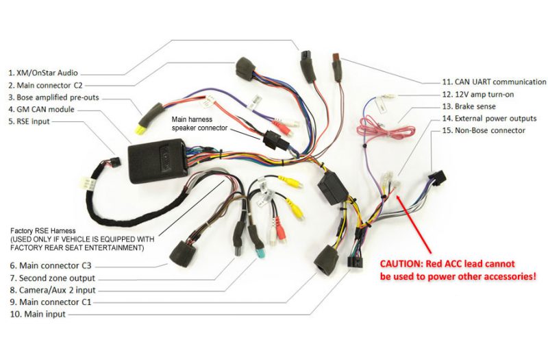
The Main Harness is the large harness that has the foam-wrapped data box attached, as well as multiple connectors that will need to be connected. This harness is used in every installation. The Main Harness Connector C1 (#9 above) will plug into the “X1” factory connector ONLY. The Main Harness Connector C2 (#2 above) will plug into the “X2” factory connector ONLY. However, due to its design, Connector C2 may also slide onto the “X3” and “X4” connectors – THIS WILL RESULT IN LOSS OF XM AND/OR FACTORY REAR ENTERTAINMENT. In the image above, the Main Harness is shown as configured for a Bose system installation (#3), but as it ships from the factory, it is ready to plug and play into a non-Bose system. If you have a Bose system, it needs to be configured as shown above using the PP-GM1210-8 harness. The black XM/OnStar audio connector (#1) will plug into the BLACK port on the GM-1210 and the CAN/UART Connector (#11) will plug into the BROWN port on the GM-1210 CAUTION:The External Power Outputs (#14) may be used to provide a fused constant 12V source (yellow) and ground (black), but the RED lead cannot support a draw of more than 500ma and cannot be used as an accessory source of power! DO NOT HOOK ANY ACCESSORIES SUCH AS A CAMERA OR REAR ENTERTAINMENT TO THE SHORT RED LEAD! UNPREDICTABLE OPERATION AND/OR SYSTEM FAILURE WILL RESULT! THIS WILL NOT BE COVERED UNDER WARRANTY! |
Data Module: |
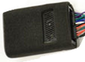 The Data Module is the source of the chimes and turn signal tones, as well as functioning as the data interpreter for the factory data bus. It comes plugged into the Main Harness and has a zip-tie wrapped around it to insure the Main Harness does not become unplugged as the adapter is inserted into the dashboard during the installation. The Data Module is the source of the chimes and turn signal tones, as well as functioning as the data interpreter for the factory data bus. It comes plugged into the Main Harness and has a zip-tie wrapped around it to insure the Main Harness does not become unplugged as the adapter is inserted into the dashboard during the installation.
If you have factory rear entertainment, you will need to plug in the small 10 pin connector on the PP-GM1210-6 harness into the end of the Data Module. To do this, slide the zip tie to one side in order to plug in the connector. Try not to remove the zip tie. Since the chime and turn signal tones will be generated by this module and their volume will be determined by its placement, you will want to test the volume BEFORE you finalize the installation. The volume can be lowered by the adjusting the placement of the module, or by wrapping foam or tape over the speaker. |
PP-GM1210-8: |
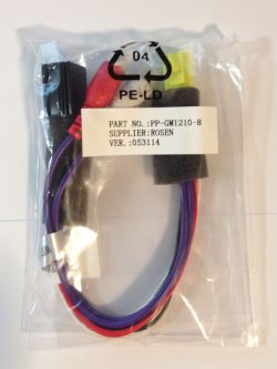 |
This is the pre-out adaptor that will be used in Bose system installations. THIS HARNESS WILL BE USED ONLY IF YOU HAVE A BOSE AUDIO SYSTEM.
The GM-1210 ships from the factory with the standard speaker connector plugged in and is ready for all non-Bose installations right out of the box. The picture of the Main Harness shows how to connect this harness for Bose system installations (#3 – Bose amplified pre-outs) – the Main Harness Speaker Connector is wrapped in foam and has a bright pink tag on it. For BOSE systems, unplug the connector with the pink tag in the main harness and plug the BLACK end of this plug into the female side of that plug. Once the BLACK plug is connected, plug the YELLOW end of this harness will plug into the YELLOW port on the rear of the GM-1210. |
PP-GM1210-7: |
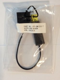 |
This is the Bose Centerpoint adaptor and will only be used if you have a Bose Centerpoint audio system.
Centerpoint is a digital amplifier system that can be identified by the presence of a center speaker on the top center of the dashboard in the LTZ or higher trim levels of the Silverado, Suburban, Tahoe and the Sierra Denali and Yukon Denali. Buick Enclave & GMC Acadia have a center speaker, but they DO NOT have the Bose Centerpoint system. Connect this harness to the brown “X4” factory connector. Once connected, the YELLOW end of this harness will plug into the YELLOW port on the GM-1210. |
PP-GM1210-6: |
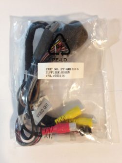 |
This is the factory rear entertainment harness. THIS WILL ONLY BE USED IF YOU HAVE THE FACTORY REAR ENTERTAINMENT SYSTEM.
This harness contains the also contains the AV2 & rear camera inputs, which will be used if you have the optional accessories. Connect this harness to the gray or black “X3” factory connector, and once connected, the green connector on this harness will plug into the GREEN port on the GM-1210 and the gray connector will plug into the GRAY port on the GM-1210. The small black 10-pin connector will plug into the end of the Data Module (move the zip tie on the Data Module to one side in order to plug it in) NOTE: If you are adding an AFTERMARKET rear entertainment system, this harness will not be used. |
PP-1007: |
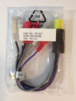 |
This is the output harness that will be used for adding aftermarket amplifiers for 4 channel and subwoofer use. This will NOT be used if your system is using the factory Bose amplifier.
This harness contains Front/Rear/Left/Right RCA outputs as well as two RCA subwoofer outputs. The yellow connector on this harness will plug into the YELLOW port on the GM-1210. |
PP-1008: |
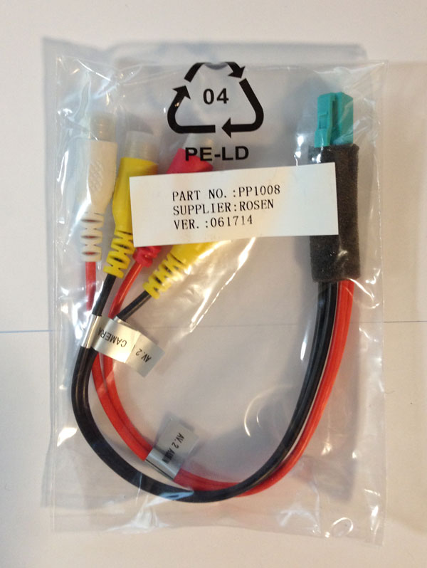 |
This is the AV2 input harness that will be used for adding an aftermarket rear camera, front camera, or inputting a hard-wired outboard A/V source. If you have the factory backup camera already and want to adapt it to the GM-1210, please see our camera support page for wiring instructions.
The green connector on this harness will plug into the GREEN port on the GM-1210. The camera is accessed via the “CAMERA” source and AV2 is accessed via the “AV2” source. The AV2 source can be switched to display on rear entertainment screens. |
PP-1009: |
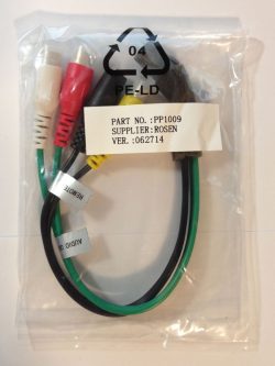 |
This is the rear entertainment output harness that would be used to display DVD/AV1/AV2 sources on aftermarket rear entertainment monitors.
The gray connector on this harness will plug into the GRAY port on the GM-1210. If you are using a Car Show or Rosen brand headrest system, the remote control input should be connected to this harness, allowing the rear seat passengers to have control of DVD playback via remote. |
PP-1012: |
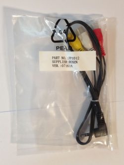 |
This is the AV1 input harness that will allow an outboard A/V source to be plugged into the 3.5mm mini headphone jack located on the face of the GM-1210. It is accessed via the “AV1” source.
The mini headphone connector on this harness will plug into the mini headphone port on the face of the GM-1210. The AV1 source can be switched to display on rear entertainment screens. |
PP-1017: |
This harness is for the optional Sirius/XM tuner and is not supplied with the unit – it is only used in a vehicle that DOES NOT have factory XM radio. In a vehicle equipped with factory XM, there are no additional connections required. However, the factory XM tuner option on the GM-1210 is not enabled by default. You must enable the factory XM tuner in the installer menu or you will not be able to choose it as a source! See the “XM TUNER SETTINGS” tab to enable the factory XM tuner. | |
Factory Harnesses: |
 Basic Connections Basic Connections |
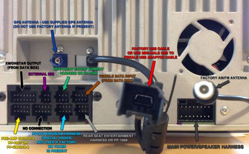
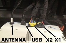
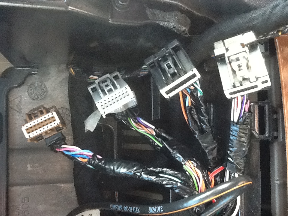
When you remove the factory radio, you will be removing multiple connectors that were plugged into the factory radio. The picture at left shows the most basic plug arrangement possible in a 2010+ GM vehicle with a factory USB jack. If your vehicle does not have a factory USB jack, the USB cable will not be present.Use this photo as a guide for the proper use of the Car Show connectors.
|
 X4/X3/X2/X1 Connectors X4/X3/X2/X1 Connectors |
Depending on your trim level and factory installed radio & accessories, your radio may also have more plugs present. NOTE: not all plugs will have exactly the same functions in all systems (especially “X4”)Use this photo as a guide for the proper use of the Car Show connectors.
|
|
Factory USB: |
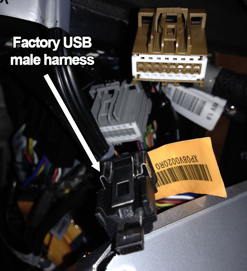 Factory mini-USB male connector Factory mini-USB male connector |
Most 2010-Up GM vehicles came with a factory USB jack, and have the factory connector shown at left. This mini-USB male connector will plug right into the mini-USB female harness on the back of the GM-1210.If your vehicle did not come with a factory USB jack and you want to use the USB input, you will have to source a USB cable and/or a USB jack of some sort. Here are some of the most common methods to connect USB:
If you need any guidance on what to purchase to accomplish any of these methods, please contact us. |
Factory Camera: |
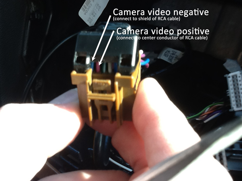 X4 Connector camera connections X4 Connector camera connections |
If you have are replacing a factory navigation system, you may have a factory camera that displays there instead of the mirror. In order to wire the camera into the GM-1210, we can supply a plug and play adaptor harness (for standard Bose systems only – not Centerpoint), or you can wire it in with a single RCA cable very easily.The camera’s video positive and negative leads are in the brown “X4” plug, pin 6 (PINK or WHITE) & pin 7 (BLUE). We will connect to these two wires with a single RCA cable. This doesn’t have to be anything fancy – just a spare RCA cable from around the house will do. Simply cut off one end of the RCA cable, then separate the center conductor and the outer copper braided wires. Connect the center conductor of the RCA cable to the PINK or WHITE wire in pin 6, and the outer copper braided wire to the BLUE wire in pin 7. You can use connectors to do this or a simple military splice. Tape up the connections to eliminate any risk of a short circuit, then plug the other end of your RCA into the rear camera input on the GM-1210 and enable the camera in the menu.For other factory camera connection options please see our Camera Support page. |
| 2007-13 Silverado LTZ w/Bose: OGM1 Installation
|
2007-13 Silverado LT: OGM1 Installation
|
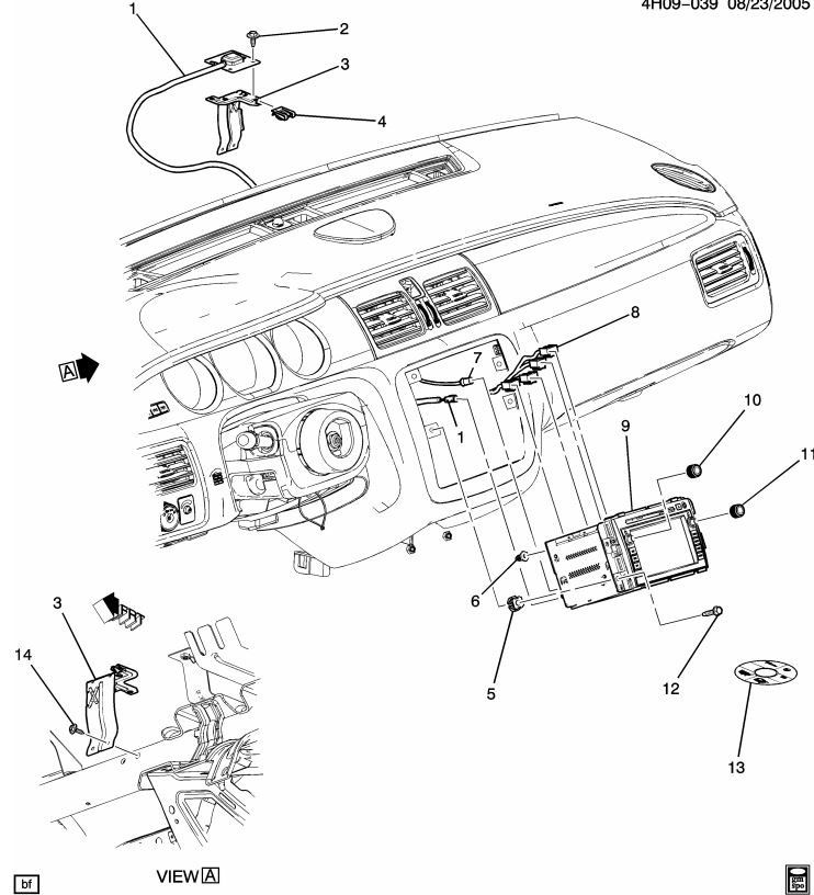
| GMC Yukon: Navigation Installation
|
GMC Acadia: Radio Removal
|
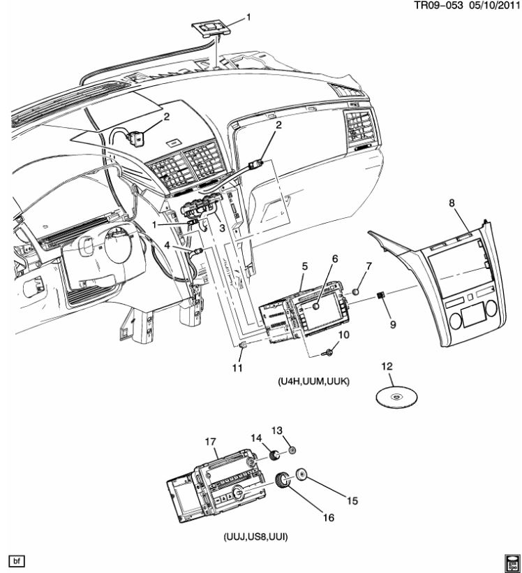
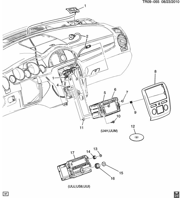
| Chevrolet Traverse: Navigation Installation
|
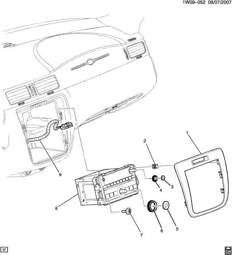
Chevrolet Impala: Radio Removal
|
| Buick Enclave: Radio Removal
|
GM Truck & SUV: Rosen Headrest DVD Installation
|
| Although the videos above do not specifically show the GM-1210 installation, they will show you how to remove the factory radio and re-assemble the vehicle. We intend to expand this section with more product-specific videos soon. | |
| NOTE: If you do not own a set of plastic trim tools as shown in the videos, Harbor Freight sells a great set for $6.99 | |
|
Silverado/Sierra-Non Bose |
Silverado/Sierra-Bose | Acadia |
 |
 |
 |
| Express/Savanna | Equinox | Impala |
 |
 |
 |
| Traverse | Lucerne | Enclave |
 |
 |
 |
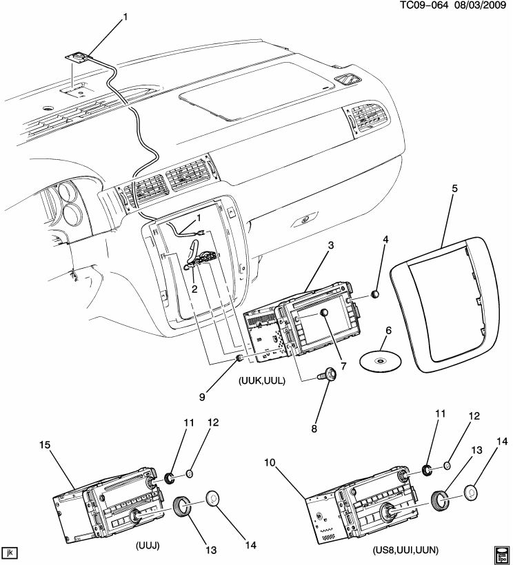
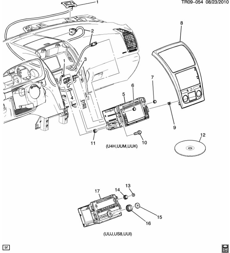
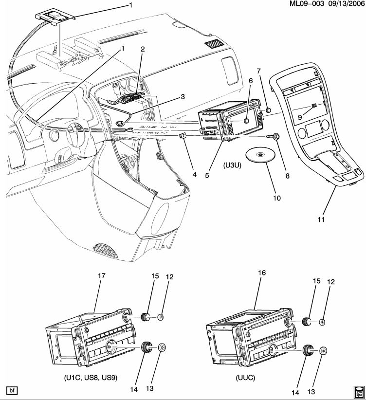
| We suggest mounting the GPS antenna in the factory location whenever possible, as this will give you a clear view of the sky without being visible, and delivering the same performance as the factory. Refer to the drawings below to locate the factory navi antenna locations: | ||
 LTZ dash navi antenna location LTZ dash navi antenna location |
 LT dash navi antenna location LT dash navi antenna location |
 Traverse navi antenna location Traverse navi antenna location |
 Silverado/Sierra GPS antenna location Silverado/Sierra GPS antenna location |
||
 Factory XM Settings Factory XM Settings |
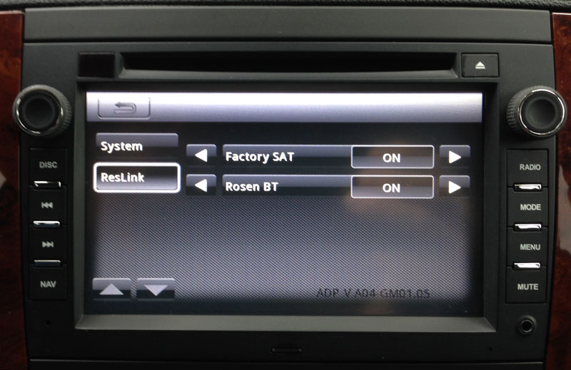
The GM-1210 can accommodate either the factory XM tuner or an aftermarket Sirius/XM tuner. The radio ships with the factory XM tuner DISABLED in the menu. In order to use your factory XM tuner, you will need to enable it first.To do this, follow these steps:
|
|
| If your XM menu button displays “SXM” instead of “SAT”, your satellite tuner is set up incorrectly and you will only be able to access one set of six presets on the factory XM tuner. The video below covers the programming required to retain the three bands of XM presets that is explained above:
|
||
| Factory Bluetooth Settings |
You have a choice to use the factory Bluetooth (if equipped) or use Bluetooth on the GM-1210. IF YOUR PHONE SUPPORTS IT, YOU MAY BE ABLE TO USE BOTH BLUETOOTH SYSTEMS SIMULTANEOUSLY.
In order to use the GM-1210’s Bluetooth system, you will need to enable it in the INSTALLER MENU first:
|
|
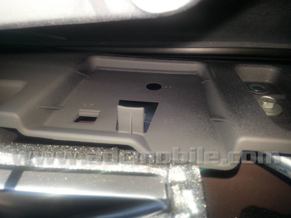
 Mic mounted on headliner Mic mounted on headliner |
Although the GM-1210 system has an internal microphone that will work acceptably (provided the vehicle is not moving), we have found that the external microphone is higher quality and sounds better, provided it is mounted correctly.
This mic is designed to be mounted in free air (free air means that both the front and the back of the mic will be open to the cabin environment) and will usually work the best when it’s mounted on a soft surface (like the headliner) and isolated from any contact with hard surfaces in the vehicle (such as dashboard, trim panels and windshield). We HIGHLY recommend the headliner location due to its isolation from vehicle vibrations, the proximity to both driver and passenger, and the distance from sources of noise in the cabin, such as open windows, A/C vents, etc. We have found it to be the best option for the vast majority of vehicles we work on. Having done literally hundreds of these installations, we recommend mounting the microphone on the headliner as shown at left, centered near the rear view mirror. Slide the “C” clip over the leading edge of the headliner, but be certain that the rear of the clip does not touch the windshield! If necessary, add a small piece of foam tape or a small square of Velcro to insulate the clip from contact with the windshield to reduce any noise that may be transmitted into the mic. You can easily route the microphone cable down the passenger side “A” pillar, then behind the glove box over to the radio. |
|
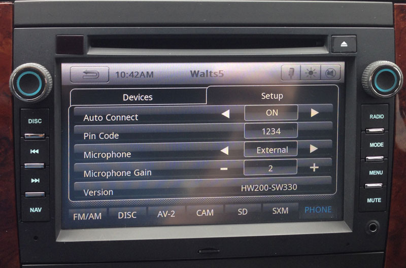 Bluetooth Sensitivity Settings Bluetooth Sensitivity Settings |
For the initial setup, we recommend to go into the settings for Bluetooth, then change the microphone setting to “EXTERNAL”, and reduce the microphone gain to between 2 and 5. Place a call while driving and experiment with the sensitivity settings to get the best response.Higher settings will boost the microphone volume, allowing the caller to hear you better, but generally results in elevated road and background noise. We have found settings under “5” work the best. | |
| There is a PINK parking brake wire that is designed to monitor the position of the parking brake and only allow video from the DVD or other outboard sources to be displayed when the parking brake is engaged.To demonstrate video while in motion, the PINK parking brake wire may be grounded to chassis ground. This will allow video to be displayed as long as this wire is grounded.IMPORTANT: This is to be used for demonstration & testing purposes, for off-road use ONLY.
DISCLAIMER: WARNING!!! WARNING!!! THIS MODIFICATION IS DESIGNED TO BE ONLY FOR OFF-ROAD USE OR WHEN VEHICLE IS IMMOBILIZED. THE DRIVER IS RESPONSIBLE FOR MAINTAINING FULL ATTENTION WHILE OPERATING A MOTOR VEHICLE. THE REMOVAL OR BYPASSING OF SAFETY FEATURE IN ROSEN/CAR SHOW PRODUCTS MAY RESULT IN PERSONAL INJURY. USING THIS FEATURE IMPROPERLY MAY RESULT IN INJURY, CITATION AND ARREST BY AUTHORITIES! ADCMOBILE.COM OWNERS AND EMPLOYEES ARE NOT RESPONSIBLE FOR UNAUTHORIZED USE. |