Advent OGM1 Camera Support
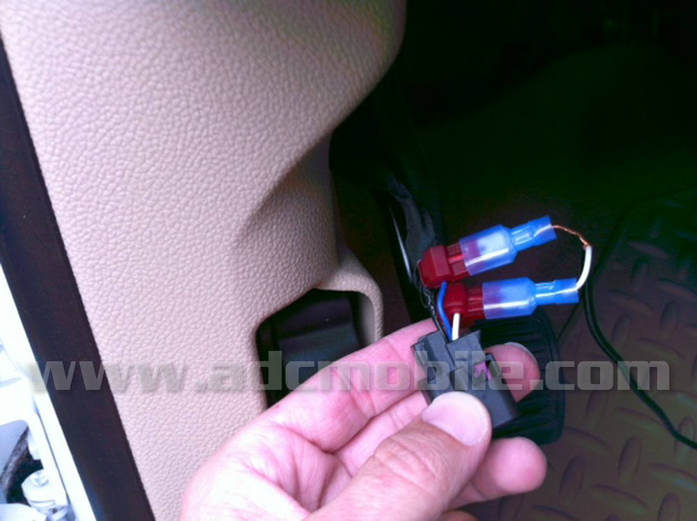
Factory Camera Wiring and Backup Sensor SetupIf your vehicle has the FACTORY rear camera already installed and playing on the factory mirror monitor (normally 2008-up ONLY), you can wire your factory camera to the OGM-1. The factory camera plug is located at the top of the left kick panel in Silverado and Sierra trucks. 2008-11: Plug has five wires on BOTTOM OF PLUG (towards floor) – See Fig. 1 No matter what year truck you have, the process is the same: to wire the factory camera to the OGM-1, connect a single RCA lead to the rear camera input on the OGM-1, then route the other end to the driver’s kick panel. Cut off the end and strip the insulation exposing the shield and center conductor. Attach the RCA’s outer shield (copper braided) to the blue wire and the RCA’s center conductor to the white wire as shown below: |
||
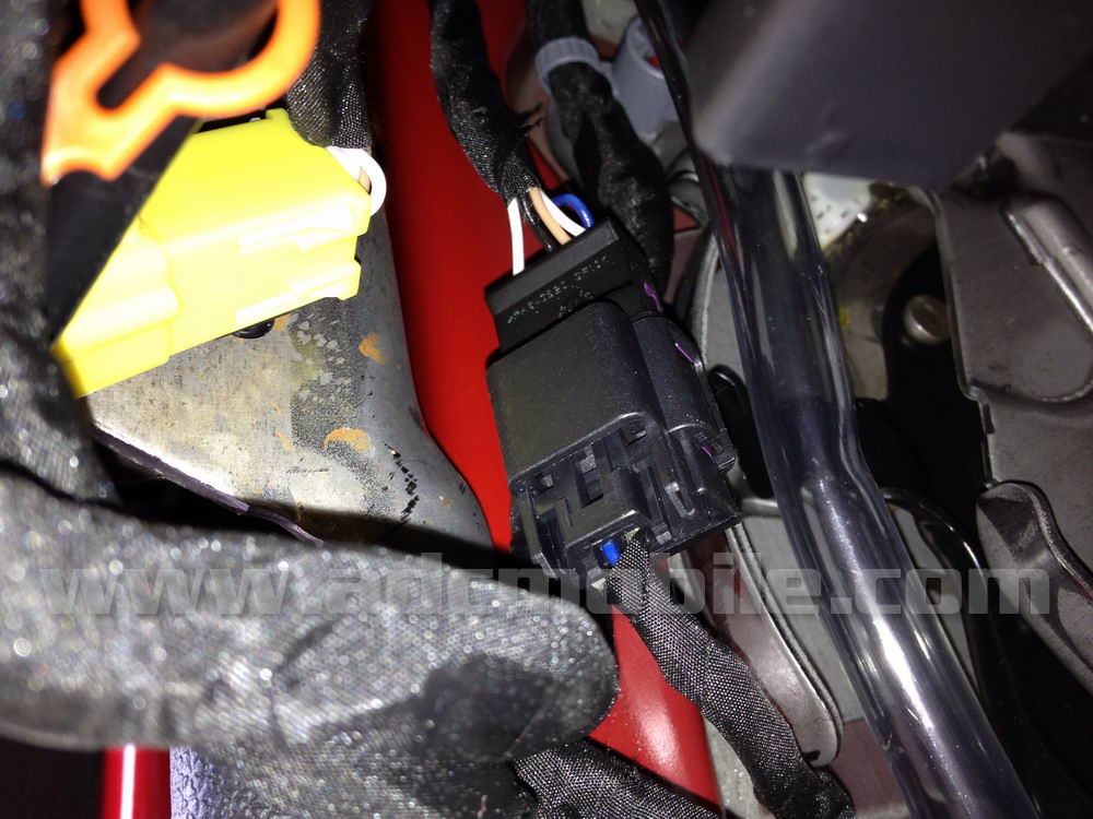
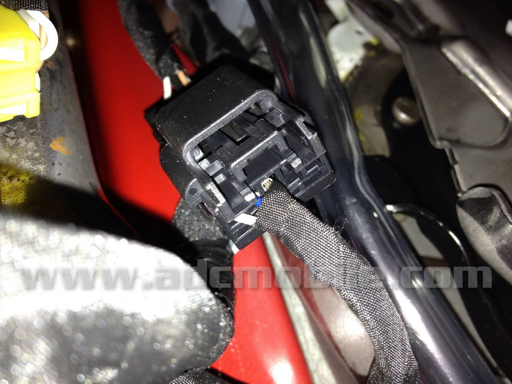
Silverado & Sierra Factory Camera Plug: |
||
 |
 |
 |
 |
 |
|
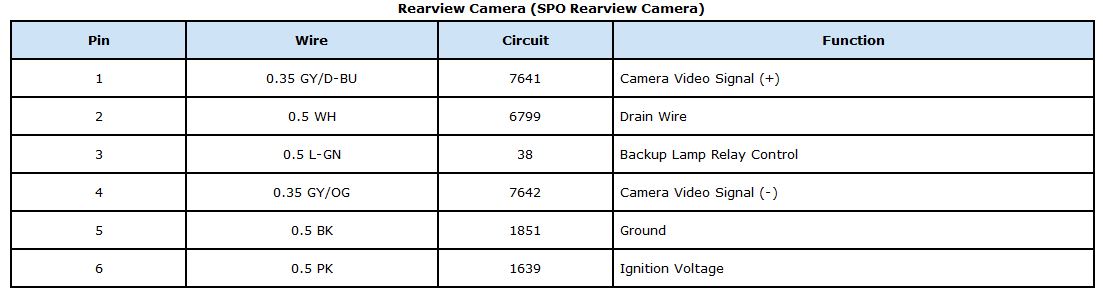
| If you wanted or needed to make connections at the rear of the truck at the camera connection itself, or wanted to wire your camera for use while driving or other on-demand use, here are the camera pin assignments: | ||
 |
 |
|
 |
 |
 |
Avalanche/Tahoe/Suburban/Yukon/Enclave Factory Mirror: |
||
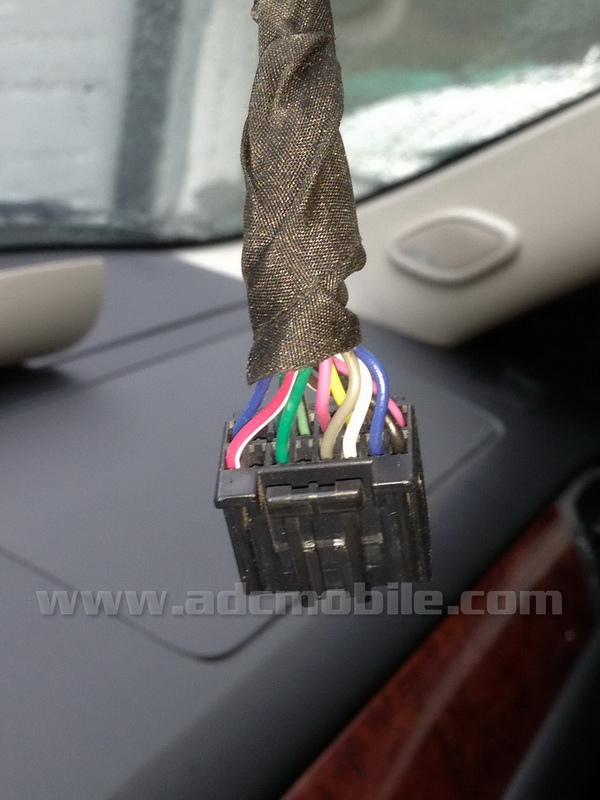
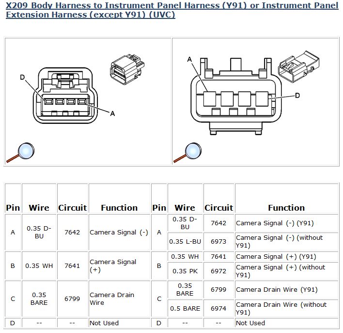
| You may have a mirror that has no easily accessible plug in this location to get the camera’s output from (see factory camera plug info below). In this case, you can always go to the back of the mirror to get the camera video positive and negative wires. These wires will be in pins 6 (usually white or pink) & 7 (usually blue) in the plug on the back of the mirror – you can also tell which wires the are because they are usually wrapped in blue foil further up the harness under the tape. If you’re doing this kind of installation, refer to these photos and the schematic on the bottom right (this shows an ’09 Enclave, but is typical for almost all GM monitor mirrors): | ||

|
 |
 |
Tahoe/Suburban/Yukon Factory Camera Plug: |
||
| On the Tahoe/Suburban/Yukon, the factory camera plug should be located in the right (passenger side) kick panel area and have the following pin assignments: | ||
 |
||
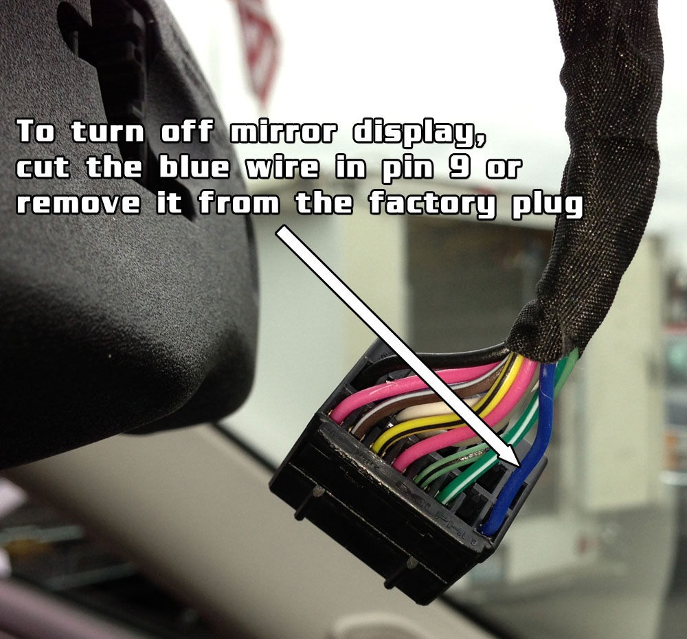
Turn Off Factory Mirror Display: |
||
| If you don’t want to have the factory mirror display the camera after you have wired the camera output to the Advent unit, you can disable the display in the mirror very easily. The trigger lead that turns on the mirror’s display is the dark blue wire in Pin 9. You can either cut and tape this lead, or preferably, unlock the tab on the bottom of the factory plug and remove the pin from the plug (so you can reinsert it at a later date if you ever remove the OGM1). If you remove the pin, just tape it to harness so it’s not flopping around. | ||
 |
||
Camera wiring when replacing factory navigation radio: |
|||
| If you are replacing a factory GM navigation unit and have the factory camera that displays on the navi screen, you can still use that camera output on the OGM1. When you remove the factory navi, you will have one plug that does not have a mate on the OGM1 harness: the brown “X4” connector, which will have three or more wires in it. In this harness, the camera leads are the wires in pin locations 6 & 7 (see schematic on left below).
If you did not purchase the adaptor harness for this plug, you can still do the camera connection very easily. In this case, you will cut off one end of a short RCA cable, strip the outer insulation and connect the RCA center conductor to the pink or white wire in pin 6 (this color will depend whether your truck has RPO code “Y91” – found on RPO code sticker in glove box) and connect the RCA shield to the lt. blue wire in pin 7. |
|||
 |
 |
||
Buick Enclave/GMC Acadia/Chevrolet Traverse camera wiring when replacing factory non-navigation radio: |
|||
| The situation may occur when you pull the factory NON-NAVIGATION radio that you’ll find FOUR factory connectors on the back of the radio (with RPO codes UQA or UQS & UK6). When you have the factory backup camera system, the camera wires MAY also included in the brown “X4” connector at the back of the radio as shown in the schematic (above right). HOWEVER, THIS IS NOT GUARANTEED – WE HAVE SEEN VEHICLES WHERE THIS IS NOT A VALID CONNECTION POINT.
The camera can be wired to the OGM1 with the center conductor of the RCA connected to the pink wire in pin 6 and and the shield of the RCA connected to the blue wire in pin 7: |
|||
 |
 |
||
Factory Parking Sensor Integration: |
|||
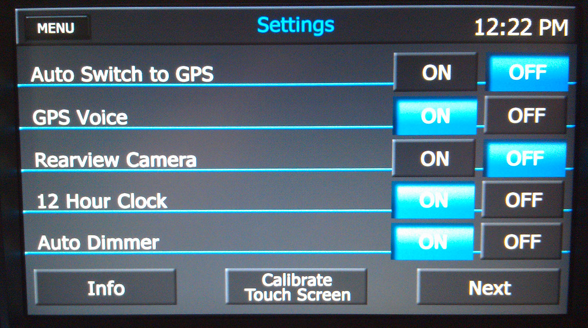
| The OGM-1 will, by default, play factory rear parking sensor AUDIO ONLY if the rear camera is not enabled. If you enable the rear camera (or add one if there is not one present from the factory), you will get a visual representation of the factory parking sensors as well:
There is no need to add any reverse trigger wire to the OGM-1, as all reverse triggering is accomplished via data through the factory harness. If your vehicle has the FACTORY parking sensors, but DOES NOT have a rear camera, we HIGHLY recommend adding a rear camera since it allows such an improvement over the factory configuration. |
|||
Factory Camera Adaptor Harnesses: |
|||
| If you are not comfortable cutting or tapping the wires discussed above, Camera Source has adaptors that can make the camera connection more “plug and play”: | |||
 |
 |
||

 |
 |
|
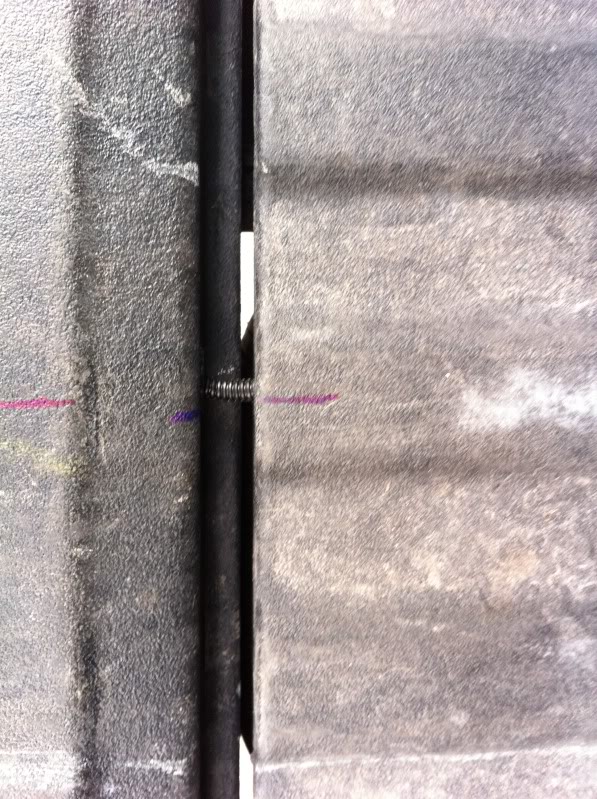
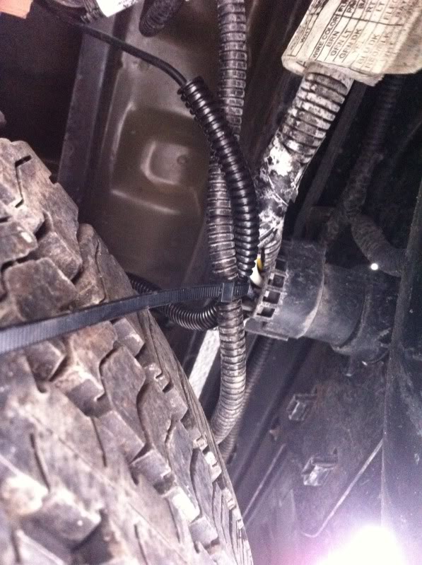
CS-GMTRB Installation Guide: If you have purchased the CS-GMTRB tailgate camera kit, download the CS-GMTRB installation manual to get more detailed information that will help familiarize you with the installation process. To start the installation, first remove your old tailgate bezel – Use the 13mm socket wrench to remove the bottom bolt of the tailgate latch – YOU DO NOT NEED TO REMOVE THE TOP TWO 13MM BOLTS. Pull the tailgate handle up out of the way with one hand and firmly grab the plastic bezel with the other and give it a good tug. Be careful, because it has a tendency to bust a knuckle on the way out. To install the camera, you will simply snap the new bezel in place and reinstall the 13mm bolt, but first you will need to run the camera cable out of the tailgate. All trucks have drain holes in the bottom of the bed, and the camera harness is small enough to pass through the center drain hole. Pass a fish tool of some sort (a coat hanger works great) through the center drain hole up to the handle area, then tape the camera lead to it and GENTLY pull the cable through the drain hole. All 2010 and newer trucks already have a 1 1/4″ hole in the back of the bed, and if yours has this, simply pass the camera cable into this hole and under the bed in preparation for connecting and running the extension harness. If you do not have a hole in the back of the bed, you have two options: drop the camera cable UNDER the back of the bed, or remove the tailgate and drill a 1″ hole into the rear panel of the bed and snap in the supplied plastic grommet, then pass the camera cable through to the area under the bed. Pull the excess wire slack under the truck. Slide the wire loom over the wire and up through the tailgate so the exposed portion between the tailgate and box is protected (shown at bottom left). Tape the loom in place and zip-tie the camera cable to an existing vehicle harness, leaving enough slack to operate the tailgate properly (center). To insure a secure, watertight connection (especially important if you launch a boat on a regular basis), source some dielectric grease and coat the male connector with it prior to plugging the male plug into the female socket of the extension harness. Connect the male and female ends of the camera harness (be careful when plugging in the camera connector – it has a keyway and only fits one way!), then tape or heat shrink the connection to seal out moisture. Run the pre-loomed camera harness alongside the factory harnesses on the left side frame rail toward the front of the truck, using the included zip ties to secure it. The easiest place to enter the cab is through the parking brake cable grommet on the driver’s side floor near the front left corner of the driver’s seat (right). To access this grommet, remove the driver’s side sill plate and peel the carpet back far enough to see the top of the grommet. Carefully pop this grommet out (it helps to push from below). You can pass the cabling through this grommet two ways: make a “X” cut in the hard rubber and pass your cables through, or cut through the outer hard plastic rim, then split the rim to pass your cables through. We suggest splitting the rim, which will allow you to pass the cables into the cab without worrying about damaging the RCA end when trying to force it through the very stiff rubber grommet. |
||
 |
 |
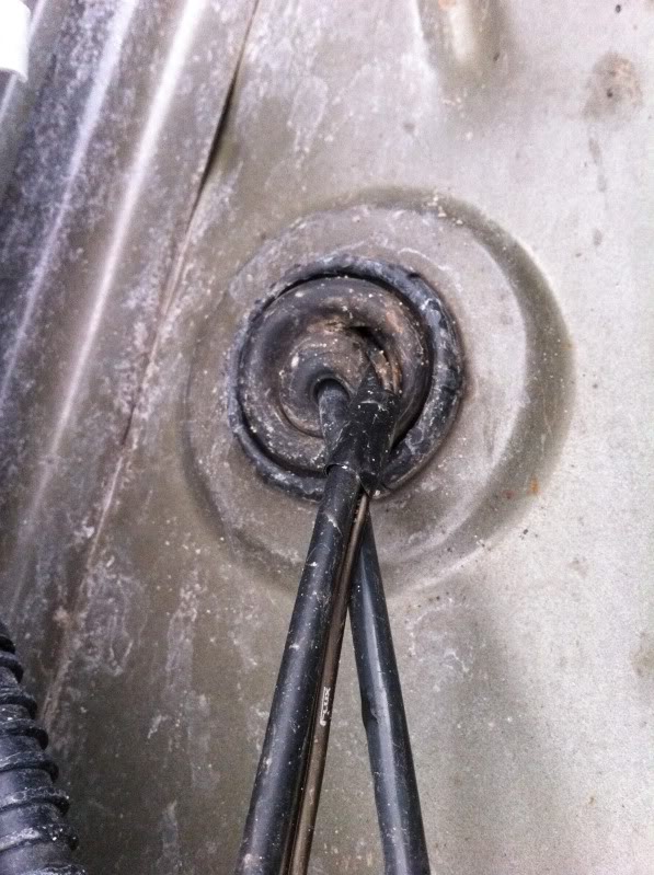 |
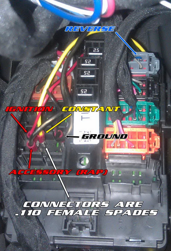
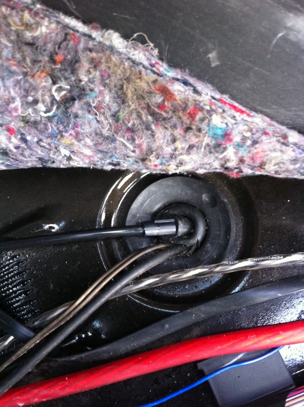
| Once you have passed your cables through the grommet, seal the grommet with some RTV (silicone) sealant to insure no leakage (below left). You can split the RCA output cable and the power/ground wires and pass the signal wire to the radio and plug it into the rear camera input female RCA. Pass the power and ground wires (red is power/black is ground) to the Left I/P Junction Block (under the square black cover to the left of the foot brake). Remove the cover by pulling out on the sides, then pull straight towards you. The camera’s red wire (power) should be wired to the dark blue REVERSE wire shown below (center), and the camera’s black wire (ground) can go to the GROUND terminal shown below (below center) or to any “bright metal” in the truck, such as under a nut or screw.
Once you enable the camera in the menu on the OGM1 (below right), start the truck and place it in reverse – it should display automatically. NOTE: Duramax diesel trucks need to be running in order to power the reverse circuit. |
||
 |
|
 |
Front camera installations |
||
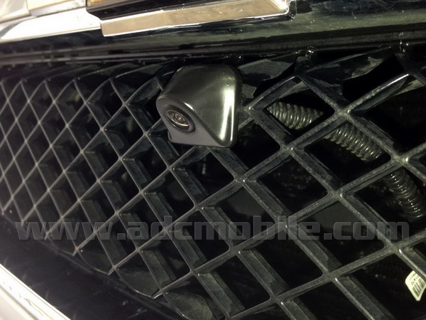
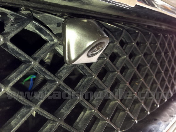
| Grille Mount:
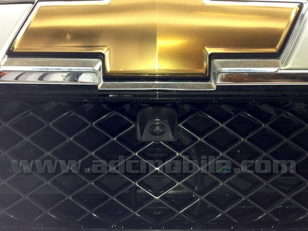
With the new Advent CAM-500 camera, front camera installations have never been easier – the pictures below show the front camera installation on our own 2011 Tahoe, and mounting this camera installation took less than five minutes. All that is required is to wrap the threads with a couple layers of electrical tape and force the camera into one of the openings in the crosshatch grille. It will be a VERY snug friction fit, that will be very stable and gives a great view over the front bumper. |
||
 |
 |
|
 |
") |
|
") |
 |
|
| Bumper Mount:
I used the Pyle PLCM37FRV camera (can also use the Advent CAM-335, which has a “front view” mode) and mounted it in the hole of the bumper and hooked into the 3.5mm ipod jack. Made a bracket out of aluminum angle and bolted that to the center bolt that holds the skirt on the bottom of bumper and added another angle to the top to make a “C” so camera could be bolted from the top . Thanks to Tom Stengle |
||
 |
 |
|
 |
 |
|
Add second camera to A/V Input for use while driving |
||
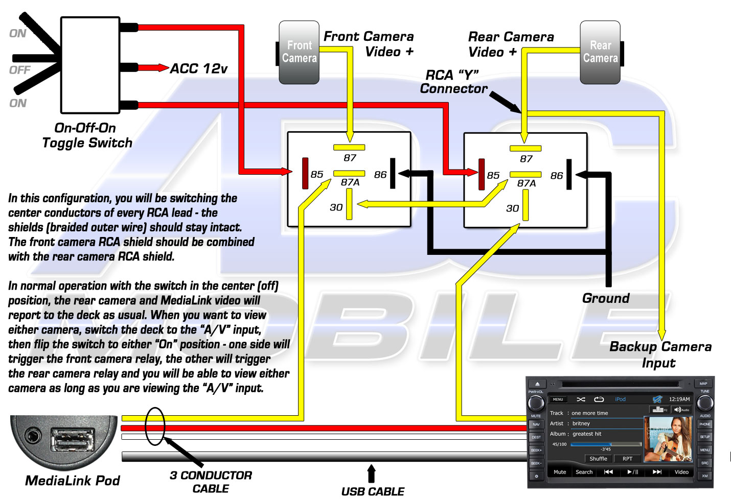
 I’ve had many requests to figure out a way to view the rear camera or to add a second camera for use while driving (to monitor the trailer hitch, snow plow, horses in horse trailer, fifth wheel hitch, etc.). While not a plug and play type of mod, the following schematic shows the simplest way to add a second camera and have it be available on demand while in motion. With the use of a standard Bosch-style relay and a single pole, single throw switch, a second video source can be switched into the A/V source of the Advent head unit and accessed with a flip of the switch: To do this mod, you need to identify the yellow and black (shield) leads on the Advent’s A/V input plug as shown above. These leads travel with the Red/White/Black leads from the MediaLink Pod up to the white input plug. You need to separate these wires so that you have a bit of slack with which to accomplish your connections. You will cut the yellow wire as shown, and using solder (or twist & tape), make your connections to the relay as shown above. The easiest way to make your second camera connection would be to use an RCA female extension as shown below, so you don’t have to cut the RCA lead off your camera – just plug it into the female half that’s attached to the relay:  Using any standard single pole, single throw (simple on-off) switch, wire it as shown so that you’re switching ground to the relay to turn it on and off (since there is 12 volts (ACC) on the other side, switching ground will turn it on & off) In this arrangement, with the relay at rest, pins 30 and 87A are connected, leaving the A/V input functioning as it was shipped from the factory – passing video from the JLINKUSB cable or other source plugged into the A/V input’s 3.5mm female jack. This lets you get video from your iPod/iPhone or whatever is plugged into the A/V jack when you switch to the A/V source on the deck. When the switch is flipped, the relay turns on and you are now connecting pins 30 and 87, sending the second camera’s video output to the A/V input of the deck, allowing you to view that camera. If you want to view the existing rear camera, simply “Y” off of that camera’s output and connect one leg of the “Y” to the relay as shown. The black lead next to the yellow in the Advent’s A/V cable is a shield for the video input. The black insulation (it’s actually heat shrink) should be stripped back and the shield of the second camera’s RCA should be connected to it. |
||
Connect Front & Rear Camera to OGM-1 via A/V Input: |
||
 |
||
Add a front camera to factory GM mirror monitorIf you have an aftermarket navigation like an Advent OGM1, Alpine or Kenwood, etc. and have tied your factory camera into the aftermarket head unit, unless you disconnected it or sold the factory display mirror, you are now left with the factory camera showing in the mirror as well as the display on the radio. Although this is a perfectly acceptable situation and in some cases may be preferable if you tend to look at the mirror while backing up, you have a couple more options available:
A front camera is a lifesaver when pulling into a tight parking stall or garage space, and for the cost (in this case less than $125, but can be done for much less), it’s cheaper than fixing ANY damage you could do to the front of your truck by running into another vehicle or other immoveable object. Also, if you ever hook any accessories to the front of your truck (snowplow, front hitch, etc.), a front camera is indispensable. To use the factory mirror with another camera is really pretty easy and can be done simply by adding a switch to turn on the display and hard-wiring your camera to the mirror. This mod covers adding a front camera (Advent CAM500) to my own Tahoe, and the process is identical in the Suburban and Yukon, but slightly different in the Silverado/Sierra, where the camera wires are actually easier to get to. An overview of the process:
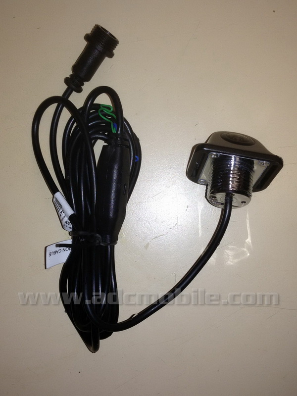
In my own Tahoe, I added an Advent CAM500 to the front grille – this is a small camera with an all-metal body that can be used as a front or rear camera and has switchable parking lines:
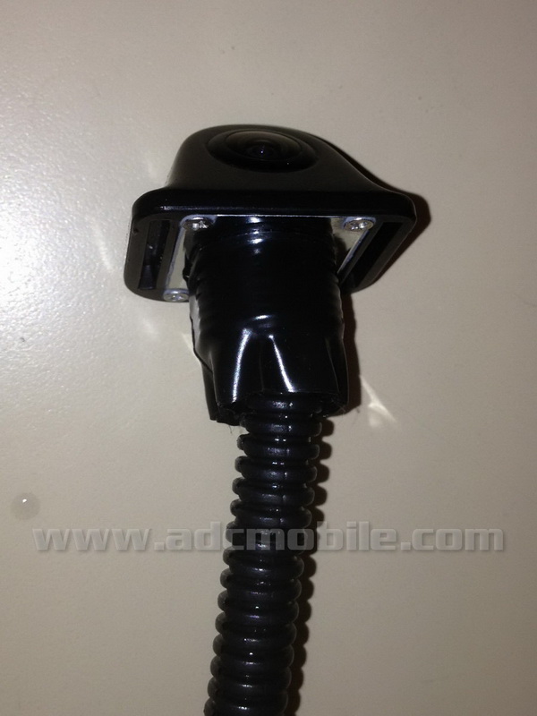
In the case of the Tahoe (or Silverado) with the factory “crosshatch” style grille, it was EXTREMELY easy to mount because the threads of the camera body were within a few thousandths of a “friction fit” into any one of the holes, so I added about 4 wraps of electrical tape to the metal threads to tighten the fit:
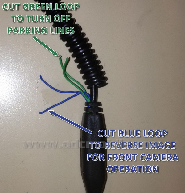
As I mentioned, the camera is able to be used as a front camera because you can cut a loop to reverse the image, and another loop to remove the parking lines:
Once the camera is mounted, it’s very unobtrusive and almost hard to pick out as an aftermarket accessory:
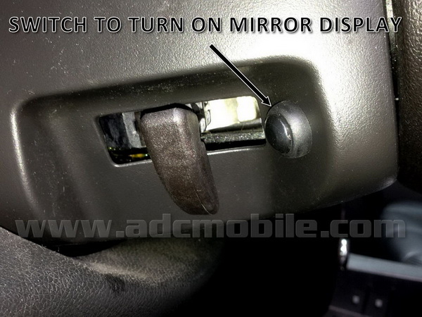
Next came finding a switch to use and a place to mount it. I sourced a nice rubber covered momentary switch, which when activated turns on the mirror display that stays on for 3-5 seconds after releasing the button. I mounted it on the steering column cover to the rear of the opening for the steering column tilt release lever:
The switch is what’s needed to turn on the mirror display while the truck is running, so it has to have an ignition power feed on one terminal (input) and a connection to the mirror display trigger wire (output) on the other terminal. A handy place to grab both ignition and the mirror trigger is at the left I/P junction block – this is under the large black cover to the left of the footbrake. Once you pull the cover off, this what you’ll see (or some minor variation of this layout):
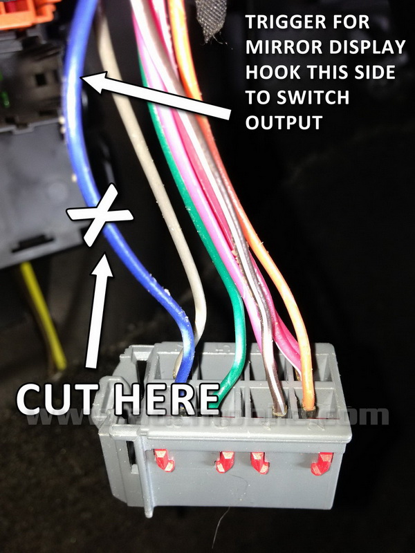
In this case, the wire labeled “REVERSE” above is in fact the trigger wire for the factory mirror, and IGNITION and GROUND for the camera and switch are readily accessible here as well. What we need to do is hook one terminal of our switch (input) to the IGNITION terminal here, then remove the light gray plug at the top right of the junction block and peel back the tape on the harness a little bit, then cut the blue “REVERSE” wire:
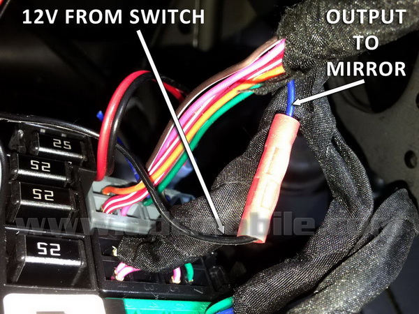
Connect the side that goes into the taped harness and up to the mirror to the output terminal of your switch:
At this stage, you can test the operation of your switch – if your factory camera is still hooked up, put the truck in reverse to turn on the factory camera, then you should be able to turn the mirror display on and off with the switch. Now we can identify the wires from the factory camera. In the Silverado and Sierra, these wires can be found at the left kick panel (and if you have already wired your rear camera to your radio, you’ve already identified these wires and hooked your radio’s backup camera RCA lead to them), or at the mirror harness like the Tahoe/Suburban/Yukon/Avalanche:
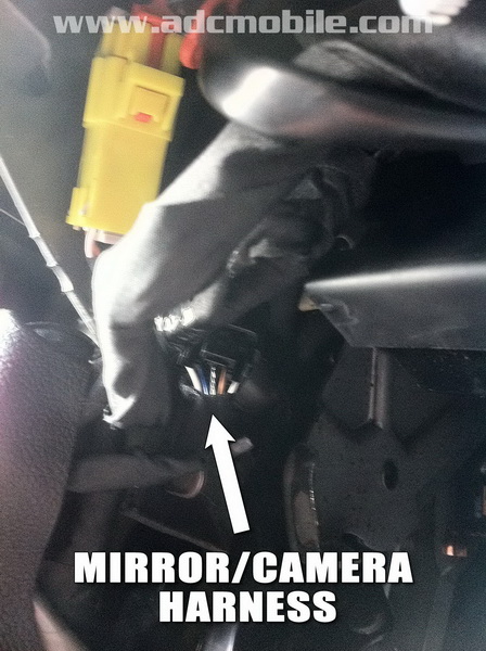
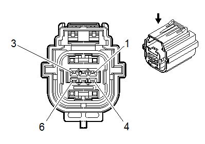
If you have a Tahoe/Suburban/Yukon/Avalanche, this camera plug is not at the kick panel – the only place I’ve ever been able to locate it is at the mirror harness itself – the factory camera wires are the white and blue wires in Pins 6 and 7 at the plug at the mirror (third and second pins in from the right, respectively in this photo):
Here’s the actual pin assignments at the mirror:
The easiest way to get access to these wires in order to make your connections is to remove the mirror (loosen the Torx T-20 screw at the base and slide it off upward), then remove the domelight lens to gain access and remove the two Torx T-15 screws under the lens, then pull out the upper console and unplug the harnesses attached, then set the console aside. You can then pull the mirror harness up and out of the hole in the headliner where the console was. Peel off the tape around the upper portion of this harness to expose the wires inside. You will need to route your camera’s video output up to the mirror in order to make these connections, and if you did not hook power to your camera at the left I/P junction block as mentioned above, you can run power and ground for the camera here as well. It is far easier to run these cables by removing the left side “A” pillar trim by pulling the trim plug at the top of the “A” pillar cover and removing the 7mm screw underneath, then pull out at the top of the trim panel, then up. Unplug the tweeter if you want, or just lay the panel on top of the dashboard. Run your camera wires up the pillar and ziptie to the existing harness that’s already there, then route across the forward edge of the headliner to the upper console location.
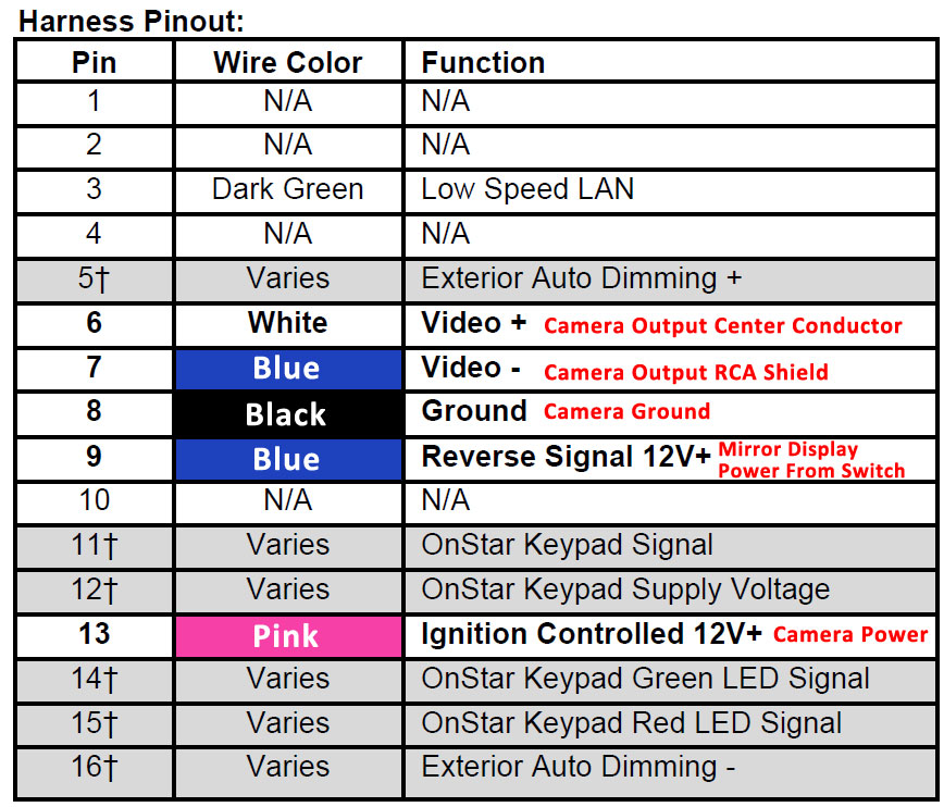
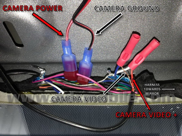
Camera power connections: IGNITION is the pink wire in Pin 13 and GROUND is the black wire in Pin 8:
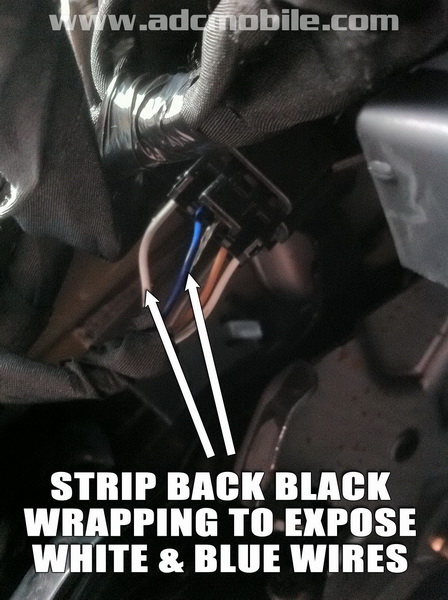
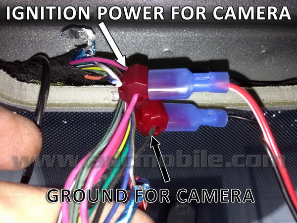
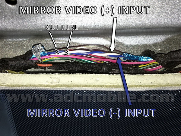
The factory camera wires are the same white and blue wires you see in Pins 6 & 7 at the mirror, but they are wrapped inside the blue foil seen here:
When you peel back the foil, the factory camera wires are inside – you will cut these wires as shown below in order to hook up your new camera input to the mirror:
Almost all cameras have a standard RCA male for video output, so it makes sense to source a female RCA cable and hardwire that to the mirror harness instead of hacking off the male end of your camera harness – in the photo below, my female RCA cable has had the outer insulation stripped off and the center conductor (RED) connected to the white wire leading to the mirror and outer shield (COPPER) has been connected to the blue wire leading to the mirror:
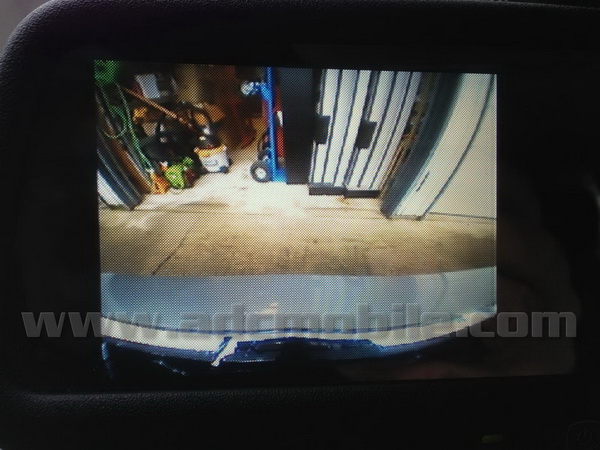
If you are doing this in a Silverado/Sierra, the same connections apply, but you will be doing them at the driver’s kick panel, with the front camera video feeding the white and blue wires leading UP THE PILLAR TOWARDS THE MIRROR. Once your connections are made, you should then be able to display the rear camera on the radio when the truck is in reverse and the front camera any time the key is on by flipping your switch. To lend some perspective of the difference this camera makes, I backed up, then pulled into my driveway as close as I dared to the front of my garage without using the camera – (close enough that I was scared of running into the house) – then switched on the camera:
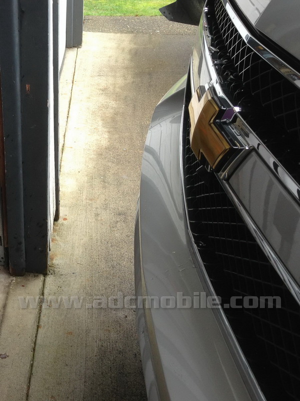
On getting out and checking my clearance, I was embarrassed at how badly I had judged the distance:
Next time, I backed up and tried pulling in with the camera on, and reduced this distance to about 6-8 inches with no problem at all. It truly made all the difference in the world being able to actually see where the front bumper was instead of having to guess (badly) where it was! In conclusion, this mod is one of the most cost-effective, useful (and fun) mods I’ve done in awhile, and it makes great use out of your factory mirror that you probably don’t even look at any more (for the camera portion anyway). |
||