Installation Video: |
|
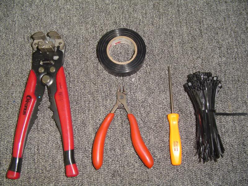
| NOTE: If you do not own a set of plastic trim tools as shown in the videos, Harbor Freight sells a great set for $6.99 |
Bluetooth microphone mounting tips: |
||||||||||||||||||||||||||||||||||||||||||||||||||||||||||||||||||||||||||||||||||||||||||||||||||||||||||
| The SYNC factory Bluetooth hands-free system has a factory microphone that CANNOT be used with the Advent navigation system – it is dedicated to the SYNC system ONLY. The microphone supplied with the OFO1501 must be used if you want to have access to the Bluetooth hands-free features built in to the Advent system. This mic is designed to be mounted in free air (free air means that both the front and the back of the mic will be open to the cabin environment) and will usually work the best when it’s mounted on a soft surface (like the headliner) and isolated from any contact with hard surfaces in the vehicle (such as dashboard, trim panels and windshield).Having done literally hundreds of these installations, we recommend mounting the microphone on the headliner as shown below, centered near the rear view mirror, using the large “C” clip that comes with the microphone. Slide the “C” clip over the leading edge of the headliner and attach the mic to the ball end. Be certain that the rear of the clip does not touch the windshield! If necessary, add a small piece of foam tape or a small square of Velcro to insulate the clip from contact with the windshield to reduce any noise that may be transmitted into the mic. You can easily route the microphone cable down the passenger side “A” pillar, then behind the glove box over to the radio. | ||||||||||||||||||||||||||||||||||||||||||||||||||||||||||||||||||||||||||||||||||||||||||||||||||||||||||
 |
 |
|||||||||||||||||||||||||||||||||||||||||||||||||||||||||||||||||||||||||||||||||||||||||||||||||||||||||
| We recommend the headliner location due to its isolation from vehicle vibrations, the proximity to both driver and passenger, and the distance from sources of noise in the cabin, such as open windows, A/C vents, etc. and have found it to be the best option for the vast majority of vehicles we work on.Back to contents | ||||||||||||||||||||||||||||||||||||||||||||||||||||||||||||||||||||||||||||||||||||||||||||||||||||||||||
Relay Basics: |
||||||||||||||||||||||||||||||||||||||||||||||||||||||||||||||||||||||||||||||||||||||||||||||||||||||||||
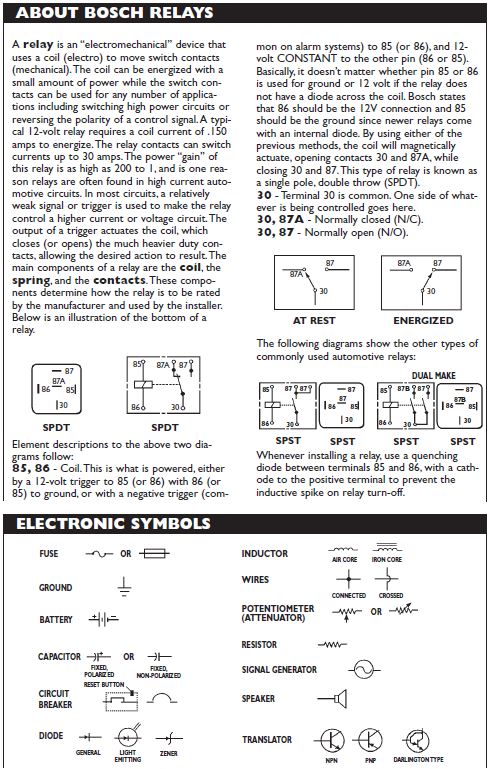 Relays have been around forever, and in the automotive environment, “Bosch” relays have become the standard, and have been widely copied. These relays are simply the best way to switch power, ground, signal, etc. in a vehicle due to their ability to carry a much higher load (30 amps) than most standard toggle switches, and their ability to be configured in just about any way imaginable to accomplish a multitude of tasks in the vehicle. Relays are really very simple devices – they usually have five terminals; 85,86, 87A, 87 & 30. At rest, the relay’s 30 and 87A terminals are connected (normally closed), allowing whatever is connected to terminal 87A to exit terminal 30 (or vice-versa). When the relay is turned on, terminal 30 is connected to terminal 87, allowing whatever is connected to terminal87 to exit terminal 30 (or vice-versa). Terminals 85 & 86 power the coil that turns on the relay – whenever there is 12 volts (ACC) on one side and ground on the other (it doesn’t matter which is 12v or ground), the relay turns on, connecting terminals 30 & 87. David Levy relay guide To learn MUCH more about the operation of relays and the cool things you can do with them, check out the David Levy Relay Guide. This 44 page guide was published in 1995, and still has dozens of great uses for relays and will help you understand how they can be used to perform many different operations. |
||||||||||||||||||||||||||||||||||||||||||||||||||||||||||||||||||||||||||||||||||||||||||||||||||||||||||
Wiring Connection Basics: |
||||||||||||||||||||||||||||||||||||||||||||||||||||||||||||||||||||||||||||||||||||||||||||||||||||||||||
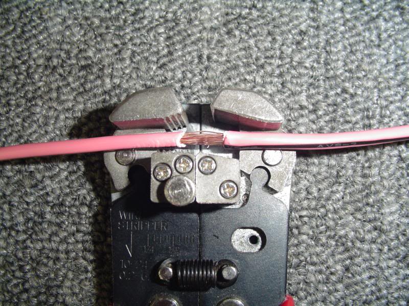
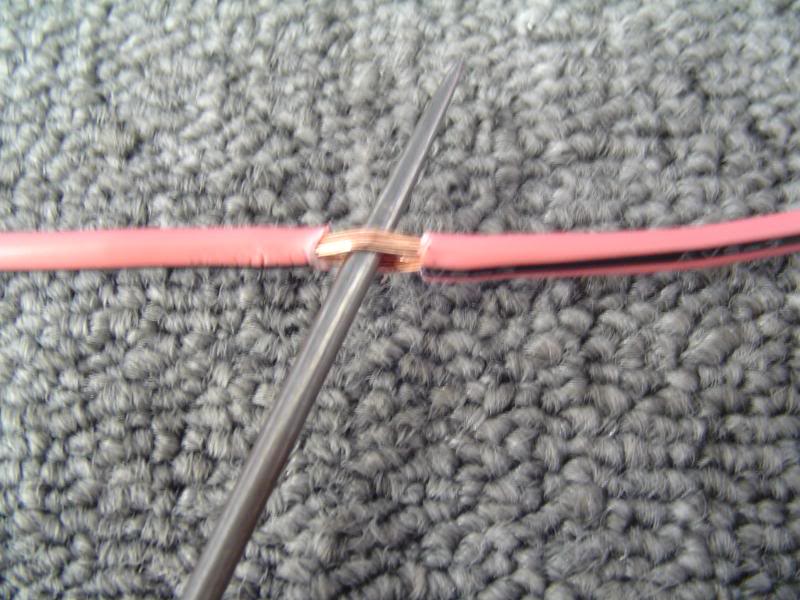
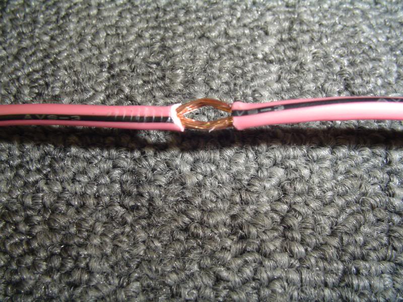
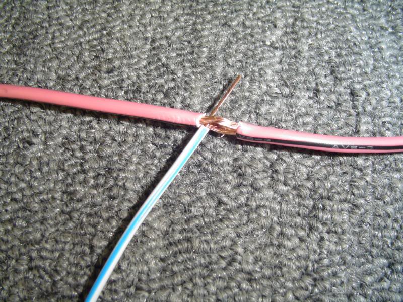
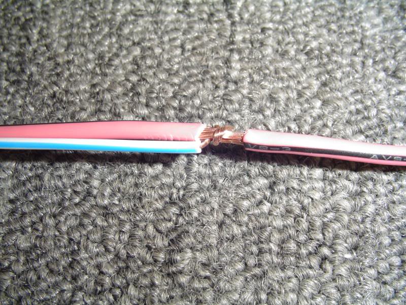
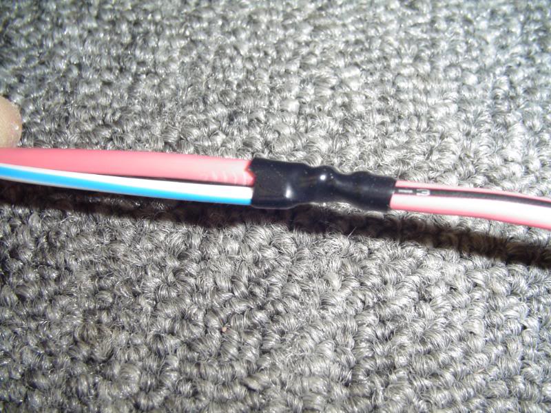
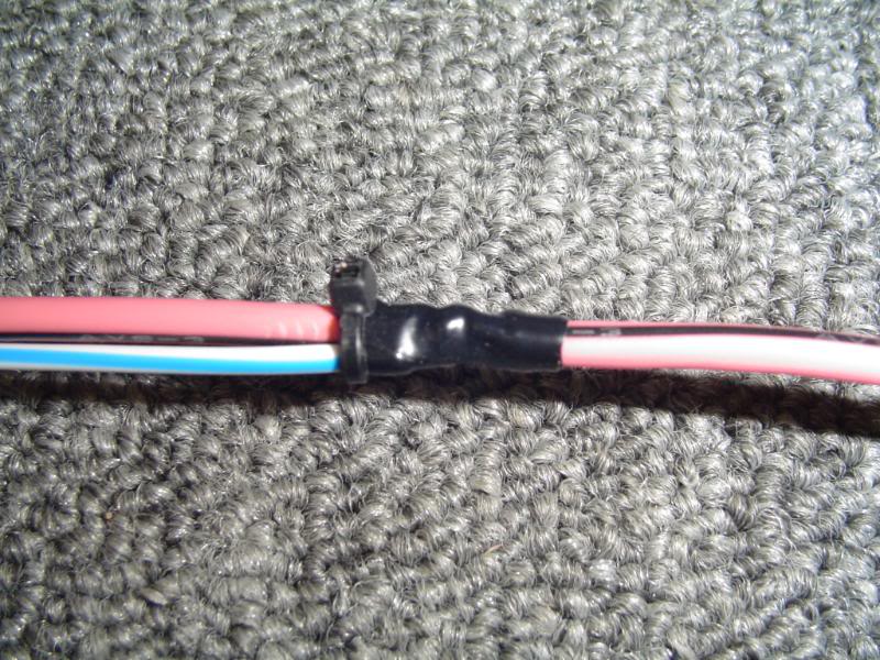
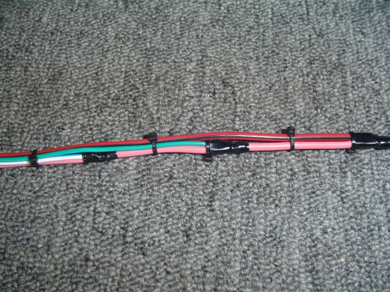
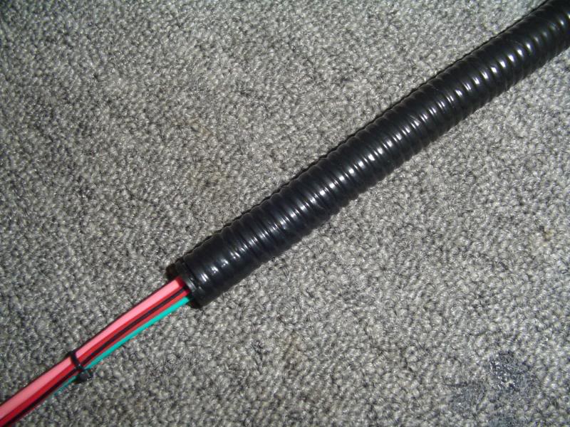
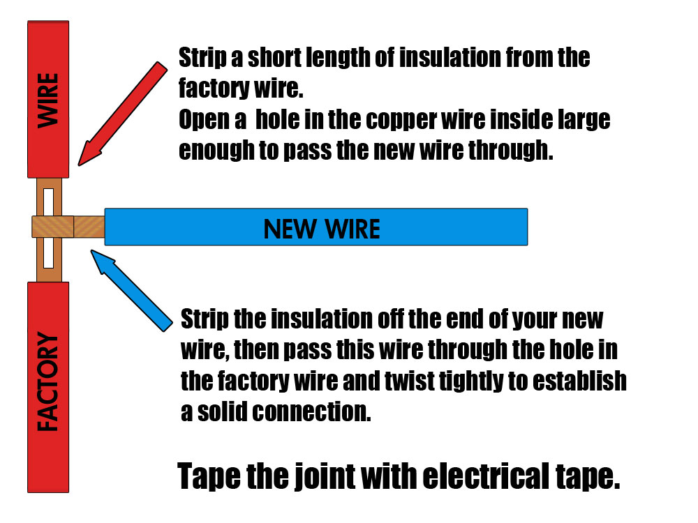 If you want to make a secure wiring connection to an existing wire in your vehicle, a very easy way to do it is to simply make a “T” connection (sometimes referred to as a Military Splice) as shown at left and below. You will simply remove a small length of insulation from the factory wire, exposing the wire inside, then split the wire enough to allow your new wire to pass through. Strip a fairly long length of insulation from the new wire, then pass the new wire trough the factory wire and twist tightly. Wrap the joint with electrical tape, and your new connection should last the life of the vehicle… |
||||||||||||||||||||||||||||||||||||||||||||||||||||||||||||||||||||||||||||||||||||||||||||||||||||||||||
Military Splice: |
||||||||||||||||||||||||||||||||||||||||||||||||||||||||||||||||||||||||||||||||||||||||||||||||||||||||||
| Posted in GM-Trucks.com by “Sinkhole”:Hello all. I posted something similar to this several years ago but I thought I’d refresh it for everyone. I always see a lot of talk about DIY installations. As an MECP Advanced certified installer most of the issues I see are due to poor installs and bad wiring connections. I just thought I post a quick little tutorial on how to make proper wiring connection, called a military splice, for those that are not sure. Many will say a soldered connection is better, but this connection has a few very important advantages over solder joints. Not to say that it is better than a soldered connection just that it has a few advantages with none of the disadvantages. First is a military splice can be undone easily if you choose to remove the equipment from the vehicle. Second you are not working with a high heat source in a confined area, thus there is no risk of accidentally melting the insulation on another wire. Also this connection is as reliable and strong as a solder connection if done properly. | ||||||||||||||||||||||||||||||||||||||||||||||||||||||||||||||||||||||||||||||||||||||||||||||||||||||||||
 |
 |
 |
||||||||||||||||||||||||||||||||||||||||||||||||||||||||||||||||||||||||||||||||||||||||||||||||||||||||
 |
 |
 |
||||||||||||||||||||||||||||||||||||||||||||||||||||||||||||||||||||||||||||||||||||||||||||||||||||||||
 |
 |
 |
||||||||||||||||||||||||||||||||||||||||||||||||||||||||||||||||||||||||||||||||||||||||||||||||||||||||
|
||||||||||||||||||||||||||||||||||||||||||||||||||||||||||||||||||||||||||||||||||||||||||||||||||||||||||
2010 F-150 Wiring |
||||||||||||||||||||||||||||||||||||||||||||||||||||||||||||||||||||||||||||||||||||||||||||||||||||||||||
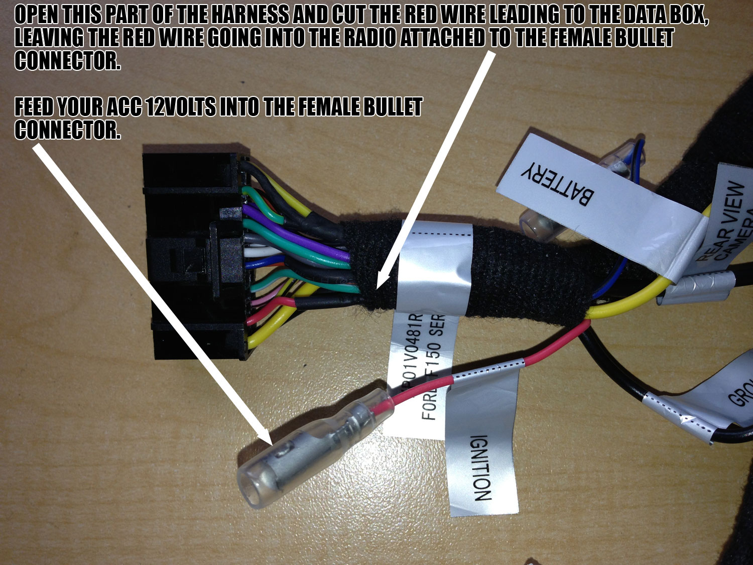
| The OFO1501 is designed to plug and play into a 2010-2013 truck that has the correct data programmed into it – if that data is there, then the radio will turn on and off properly, SYNC will work, steering wheel controls will work, Bluetooth will work, and if you had a reverse camera the triggering will happen automatically.In some 2010 model year trucks (though not all), we have seen that data not be available, which means that although you will be able to bolt in the radio perfectly fine and it will turn on, but it will not turn off since the data is not there to control and the functions listed above will not work.
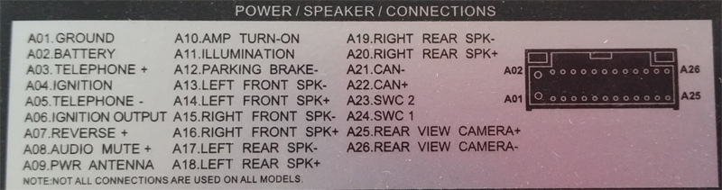
You can definitely wire in the correct accessory circuit, reverse trigger and illumination circuit for the radio. However, if that data is not there, there is nothing we can do to enable your steering wheel controls and SYNC – these will be nonfunctional. Here are the steps to get the deck wired into a 2010 truck – REFER TO THE “ADVENT CONNECTIONS” PICTURE BELOW LEFT FOR RADIO WIRING, AND ALWAYS TEST THE FUNCTION OF EVERY WIRE YOU TAP INTO IN THE VEHICLE – WE ARE NOT RESPONSIBLE FOR DAMAGE DONE TO THE RADIO OR THE VEHICLE IF YOU ATTEMPT THESE MODIFICATIONS:
|
||||||||||||||||||||||||||||||||||||||||||||||||||||||||||||||||||||||||||||||||||||||||||||||||||||||||||
Factory Camera Wiring |
||||||||||||||||||||||||||||||||||||||||||||||||||||||||||||||||||||||||||||||||||||||||||||||||||||||||||
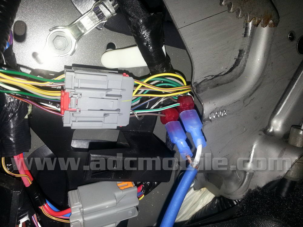
| On those trucks equipped with the factory camera display in the mirror, the factory camera’s output can be routed to the OFO1501’s backup camera input. This is easily accomplished by chopping one end off a standard RCA cable, stripping the outer insulation, and connecting the center conductor of the RCA to the video+ lead (Pin 8) and the shield of the RCA cable to the video- wire (Pin 16) at the rear view mirror or left kick panel (thanks to James Bankston for photos below!), then routing the cable to the OFO1501 and plugging the cable into the backup camera female RCA input: | ||||||||||||||||||||||||||||||||||||||||||||||||||||||||||||||||||||||||||||||||||||||||||||||||||||||||||
 |
 |
 |
||||||||||||||||||||||||||||||||||||||||||||||||||||||||||||||||||||||||||||||||||||||||||||||||||||||||
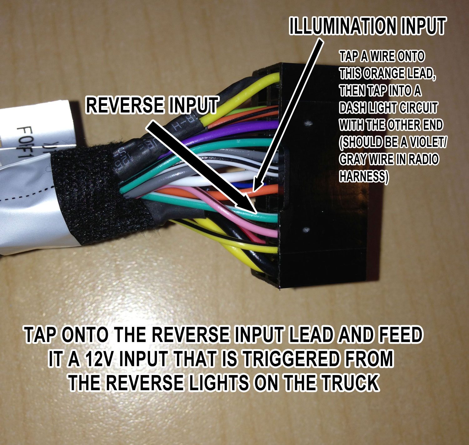
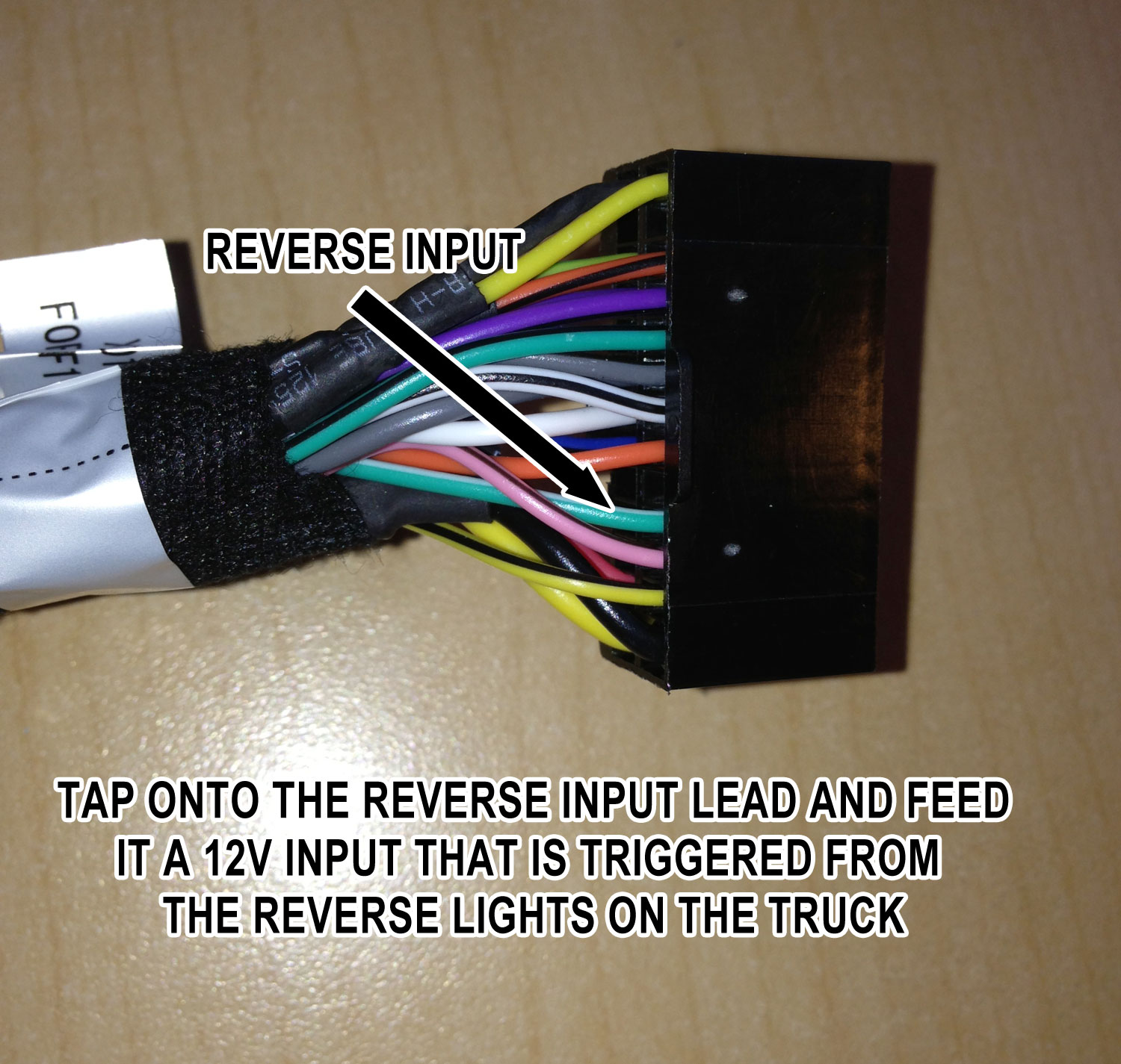
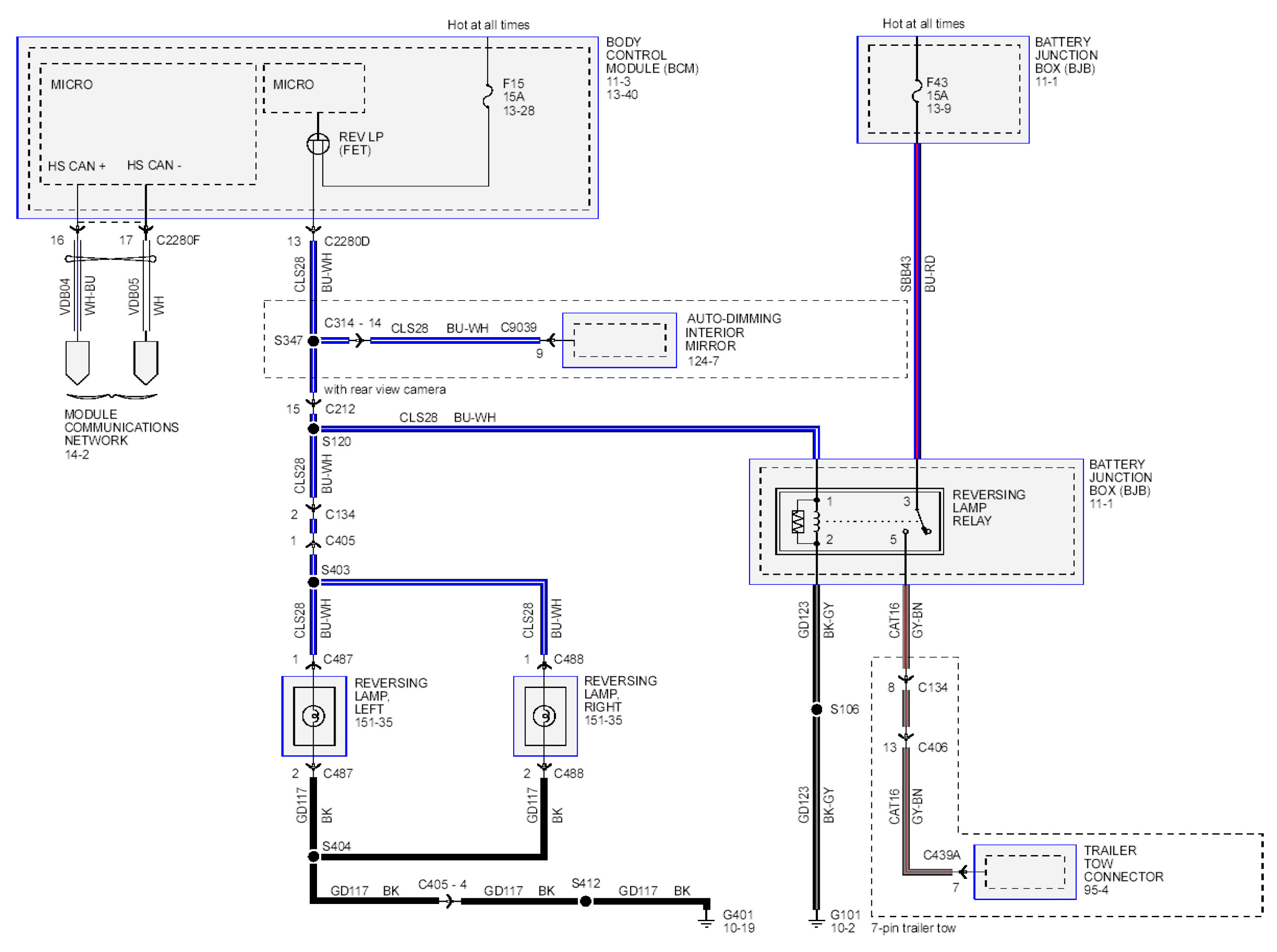
The OFO1501 is set up to get its reverse trigger lead from the databus on the truck, sending a 12v output from the data module on the green/white wire as shown below:
However, we have learned that not all F150’s have this data feed for the reverse trigger. If your truck DOES NOT have the data feed for the reverse trigger, you will have to manually trigger the reverse input wire. An easy way to tell if the truck has the data feed is to plug in the deck and turn on the backup camera input in the main menu. Start the truck and put it in reverse. If the display DOES NOT switch to the backup camera input (if no backup camera is connected, you will see a “Video source not detected” error), you will have to wire this input manually. To do this, connect a wire from the reverse light wire on the mirror (blue/white – Pin 9) to the green/white reverse trigger input wire as shown below:
Trucks equipped with the factory mirror monitor should have reverse light lead already wired to the mirror as show in the schematic below. This schematic shows the correct wire to tap (blue/white in Pin 9) on a 2012 F-150, and similar wires (if not the same colors) should be present on every display mirror:
|
||||||||||||||||||||||||||||||||||||||||||||||||||||||||||||||||||||||||||||||||||||||||||||||||||||||||||
Aftermarket Camera Power and Ground Connections |
||||||||||||||||||||||||||||||||||||||||||||||||||||||||||||||||||||||||||||||||||||||||||||||||||||||||||
Since the OFO1501 gets its reverse trigger through the databus of the vehicle, it is not necessary to wire a reverse trigger lead in Ford trucks (EXCEPT AS NOTED ABOVE). All that’s required to add a backup camera is to add the camera, power it up, plug in the RCA video output lead to the OFO1501’s reverse camera input RCA, and enable the camera in the menu.We sell a factory-style “Blue Oval” camera kit that replaces the factory tailgate bezel with new bezel and better-than-factory camera. This camera connects to the OFO1501 with an RCA input.When you install this kit, keep in mind that the factory tailgate blue oval is held on with two sided tape, so use a heat gun and the included fishing line to work the old emblem off the surface of the tailgate. On older models you will need to drill an access hole for the camera to pass through the surface of the tailgate – drilling template included. You will also need to drill a hole in the back of your bed for the camera harness to pass through. The instructions walk you through the entire installation process step-by-step.The wire harness has a single point weather resistant connection that connects to the camera near the spare tire under the truck – allows for easy tailgate removal! The harness is 25′ long so all connections can be made inside the cab if desired. Power and ground connections can be made at the back of the radio, while the RCA output cable will plug directly into the RCA camera input cable on the OFO1501.Here are some alternate power connections that can be used to power this camera kit:
|
||||||||||||||||||||||||||||||||||||||||||||||||||||||||||||||||||||||||||||||||||||||||||||||||||||||||||
System SetupWhen installing the Advent “OE” style navigation systems, there are some steps to take to insure that the installation is done correctly:
|
||||||||||||||||||||||||||||||||||||||||||||||||||||||||||||||||||||||||||||||||||||||||||||||||||||||||||
 |
||||||||||||||||||||||||||||||||||||||||||||||||||||||||||||||||||||||||||||||||||||||||||||||||||||||||||
|
||||||||||||||||||||||||||||||||||||||||||||||||||||||||||||||||||||||||||||||||||||||||||||||||||||||||||


|
||||||||||||||||||||||||||||||||||||||||||||||||||||||||||||||||||||||||||||||||||||||||||||||||||||||||||
DEMO MODEThere is a demo mode that allows the parking brake to be overridden, allowing DVD or iPod video video to be viewed while the vehicle is in motion – this is to be used for demonstration & testing purposes, for off-road use ONLY.
DISCLAIMER: WARNING!!! WARNING!!! THIS MODIFICATION IS DESIGNED TO BE ONLY FOR OFF-ROAD OR WHEN VEHICLE IS IMMOBILIZED. THE DRIVER IS RESPONSIBLE FOR MAINTAINING FULL ATTENTION WHILE OPERATING A MOTOR VEHICLE. THE REMOVAL OR BYPASSING OF SAFETY FEATURE IN ADVENT PRODUCTS MAY RESULT IN PERSONAL INJURY. USING THIS FEATURE IMPROPERLY MAY RESULT IN INJURY, CITATION AND ARREST BY AUTHORITIES, THEREFORE ADCMOBILE.COM OWNERS AND EMPLOYEES ARE NOT RESPONSIBLE FOR UNAUTHORIZED USE. |
||||||||||||||||||||||||||||||||||||||||||||||||||||||||||||||||||||||||||||||||||||||||||||||||||||||||||
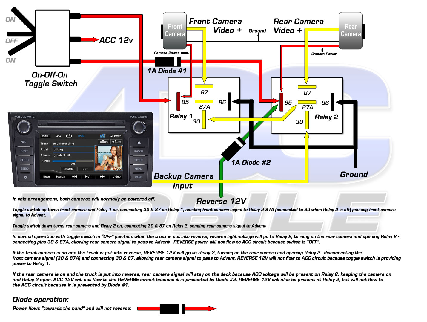
I’ve had many requests to figure out a way to view the rear camera or to add a second camera for use while driving (to monitor the trailer hitch, snow plow, horses in horse trailer, fifth wheel hitch, etc.). While not a plug and play type of mod, the following schematic shows the simplest way to add a second camera and have it be available on demand while in motion. With the use of a standard Bosch-style relay and a single pole, single throw switch, a second video source can be switched into the A/V source of the Advent head unit and accessed with a flip of the switch:
 RELAY BASICS: At rest, the relay’s pin 30 and 87A are connected, allowing whatever is connected to pin 87A to exit pin 30. When the relay is turned on, pin 30 is connected to pin 87, allowing whatever is connected to pin 87 to exit pin 30. Pins 85 & 86 turn on the relay – as long as there is 12 volts (ACC) on one side and ground on the other (it doesn’t matter which is 12v or ground), the relay turns on, connecting pins 30 & 87. To do this mod, you need to identify the yellow and black (shield) leads on the Advent’s A/V input plug as shown above. These leads travel with the Red/White/Black leads from the MediaLink Pod up to the white input plug. You need to separate these wires so that you have a bit of slack with which to accomplish your connections. You will cut the yellow wire as shown, and using solder (or twist & tape), make your connections to the relay as shown above. The easiest way to make your second camera connection would be to use an RCA female extension as shown below, so you don’t have to cut the RCA lead off your camera – just plug it into the female half that’s attached to the relay:  Using any standard single pole, single throw (simple on-off) switch, wire it as shown so that you’re switching ground to the relay to turn it on and off (since there is 12 volts (ACC) on the other side, switching ground will turn it on & off) In this arrangement, with the relay at rest, pins 30 and 87A are connected, leaving the A/V input functioning as it was shipped from the factory – passing video from the JLINKUSB cable or other source plugged into the A/V input’s 3.5mm female jack. This lets you get video from your iPod/iPhone or whatever is plugged into the A/V jack when you switch to the A/V source on the deck. When the switch is flipped, the relay turns on and you are now connecting pins 30 and 87, sending the second camera’s video output to the A/V input of the deck, allowing you to view that camera. If you want to view the existing rear camera, simply “Y” off of that camera’s output and connect one leg of the “Y” to the relay as shown. The black lead next to the yellow in the Advent’s A/V cable is a shield for the video input. The black insulation (it’s actually heat shrink) should be stripped back and the shield of the second camera’s RCA should be connected to it. |
||||||||||||||||||||||||||||||||||||||||||||||||||||||||||||||||||||||||||||||||||||||||||||||||||||||||||
Add Front & Rear Cameras via backup camera input |
||||||||||||||||||||||||||||||||||||||||||||||||||||||||||||||||||||||||||||||||||||||||||||||||||||||||||
 |
||||||||||||||||||||||||||||||||||||||||||||||||||||||||||||||||||||||||||||||||||||||||||||||||||||||||||
TROUBLESHOOTING TIPS: |
||||||||||||||||||||||||||||||||||||||||||||||||||||||||||||||||||||||||||||||||||||||||||||||||||||||||||
|
||||||||||||||||||||||||||||||||||||||||||||||||||||||||||||||||||||||||||||||||||||||||||||||||||||||||||
How to install custom splash screens |
||||||||||||||||||||||||||||||||||||||||||||||||||||||||||||||||||||||||||||||||||||||||||||||||||||||||||
Hydro-Dip the Faceplate |
||||||||||||||||||||||||||||||||||||||||||||||||||||||||||||||||||||||||||||||||||||||||||||||||||||||||||
The OFO1501 comes with a black plastic crosshatch pattern trim bezel to match exactly the bezel found on base model F-150s. However, if you don’t like that finish or have a different trim package in your truck, this bezel may be hydro-dipped to match your current trim.Hydrodip.com has a process where the bezel can be dipped to apply just about any pattern with perfect coverage on all surfaces of the bezel:
 Check out all the patterns available, and if you do decide to hydro-dip your bezel, please email us a photo when you’re done so we can share with others! |
||||||||||||||||||||||||||||||||||||||||||||||||||||||||||||||||||||||||||||||||||||||||||||||||||||||||||